A-term of 2019, I began my Light Art Practicum to complete my humanities requirement at WPI. I had to begin thinking about what I wanted my project to be. I knew I wanted to do something unique, something where I could incorporate different aspects of my learnings and hobbies. Being the mechanical engineering that I am, I wanted to design some kind of device that created light with art. I then thought to myself, what if I could control where a laser pointer is pointing and doing something with that. I also wanted it to be interactive and adaptive. I finally decided that I wanted to create a Laser “Etch-a-sketch.”
The Initial Idea
The Laser “Etch-a-sketch” would allow a user to draw on any surface using two dials. These two dials would manipulate the XY coordinate of the laser pointer, effectively creating an “Etch-a-sketch.” After the user has finished drawing, the Arduino Nano would then quickly “playback” what the user has drawn creating a persistence of vision effect. I could add more features down the road, but the main feature was the interactive drawing and playback with the persistence of vision effect.
The Design
The plan was to use the following components:
- Arduino Nano for the brains of the project
- Breadboard for mounting and wiring all the components
- 2 – High-Speed Servos for manipulating the XY coordinate of the laser
- Laser Diode
- 2 – 1″ Mirrors
- Pololu Mini Maestro 18 for the servo driver
- 5V 2A Wall Wart
- 2 – Potentiometers
- 2 – Push Button
The idea was to use the high-speed servos with mirrors oriented in a specific way that allowed each servo to control one of the axes. The potentiometers would control the position of each servo such that one potentiometer would control the x-axis and the other the y-axis of the laser diode. I designed the base, mounts, and controller in SolidWorks and 3D Printed the parts on my Creality CR-10S. Below are the pictures of the final design in SolidWorks as well as some screenshots from the slicer is was using for 3D printing (Cura 4.0.0 with Creawesome Mod).

Full Assembly of Laser “Etch-a-sketch” 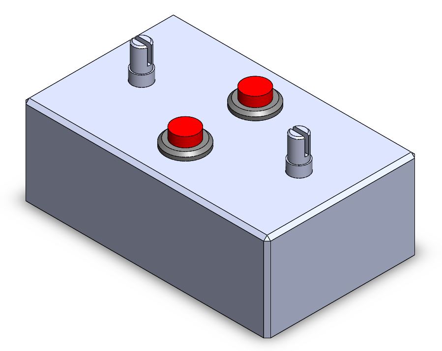
Control Box with Potentiometers and Pushbuttons 
Front View of Laser “Etch-a-sketch” 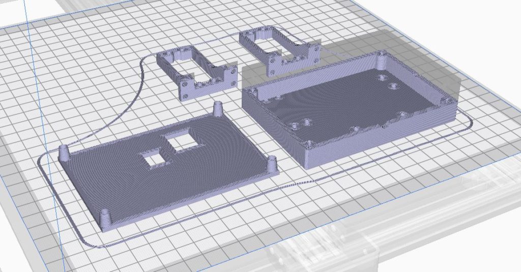
Snapshot from Cura 4.0.0 used for 3D Printing
The Wiring
Below, is a picture of the wiring diagram created in Fritzing. The Arduino is the main control unit where the processing takes place. The potentiometers are wired into the analog inputs. The buttons are wired into the digital inputs. The Red LED (Laser Diode) is wired into a digital output. What is not shown in the diagram in Fritzing, the servos are connected to a Mini Maestro 18 (shown below). The Arduino Nano communicates with the Mini Maestro 18 using a Serial connection via the TX pin on the Arduino. The Mini Maestro 18 receives 5V 2A from a wall wart to power the two servos.

Snapshot of Fritzing 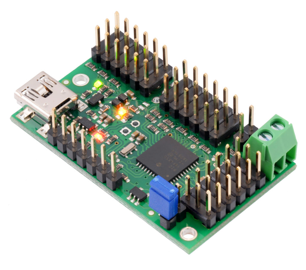
Pololul Mini Maestro 18
The Final Idea
Originally, the idea was for the user to draw with the potentiometers and for the “Etch-a-sketch” to quickly redraw the users’ input in order to create a persistence of vision effect. This didn’t work perfectly so I worked on other artistic effects I could create with lasers. I was able to create geometric and abstract shapes. The geometric shapes I could create were lines, triangles, squares, and circles. For the abstract shapes, the two servos would sweep between their minimums and maximums. In the abstract mode, the potentiometers would control the speed at which each individual servo would sweep. This would create some abstract shapes that were unique and changing as the two servos wouldn’t sweep at the same speed.
The Final Product
Below are some pictures of the final Laser “Etch-a-sketch.”
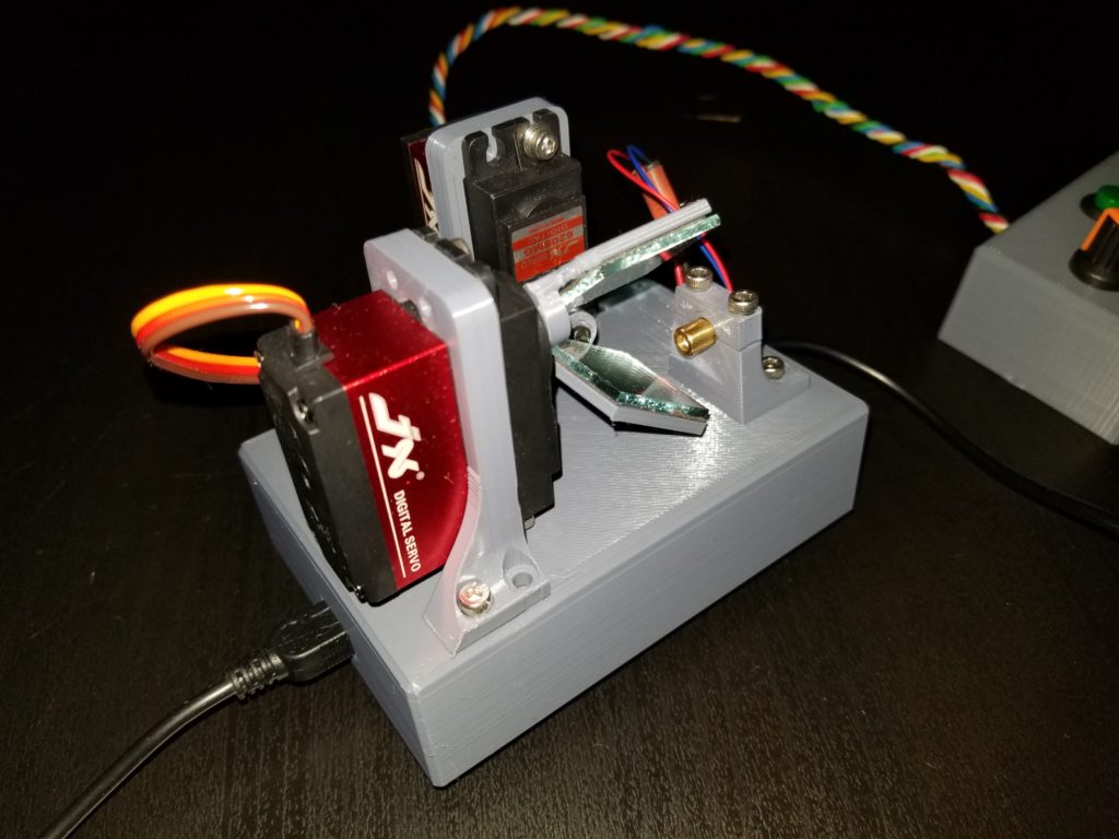


Fully Assembled 
Controller with Potentiometer and Buttons
The Drawings
Below are some pictures of some of the drawings that the Laser “Etch-a-sketch” created in user drawing mode and geometric shape mode. All of the pictures were taken at 1-second exposure.
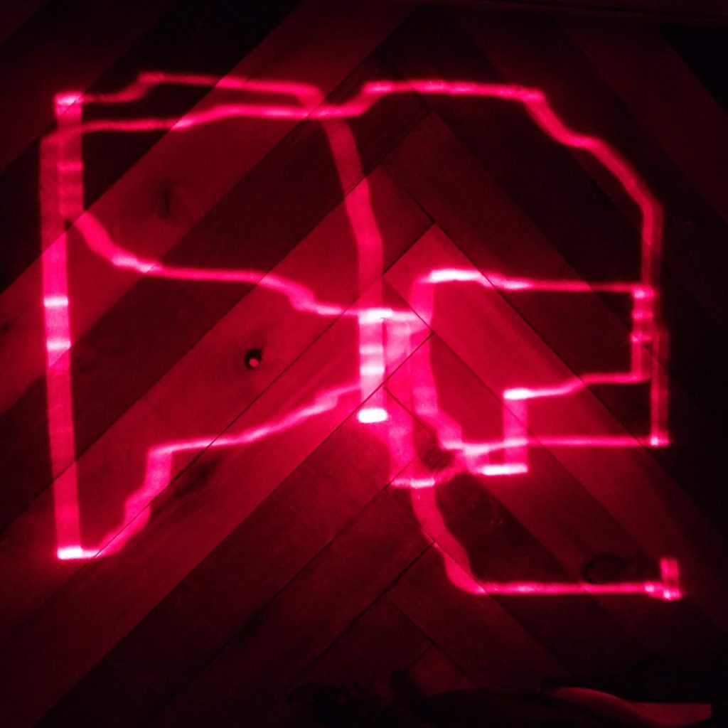
User Drawn 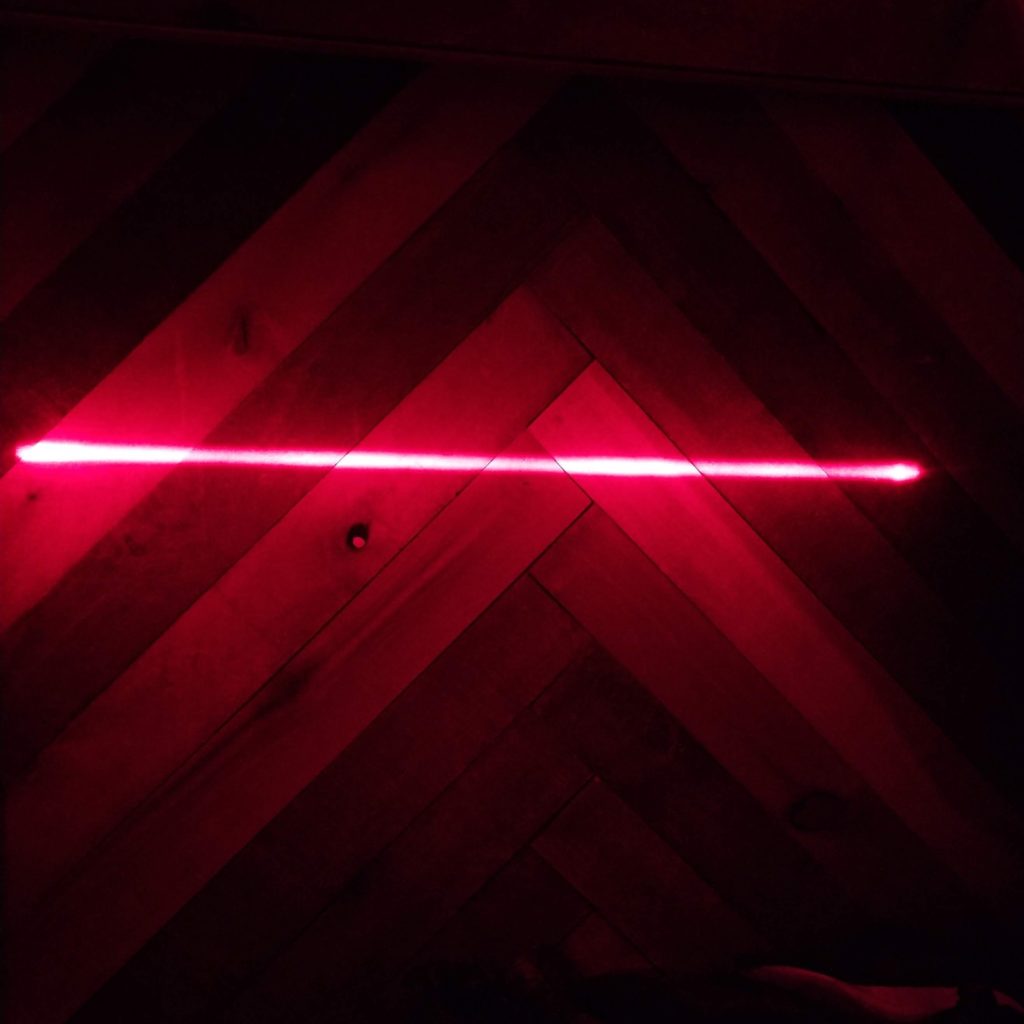
Line 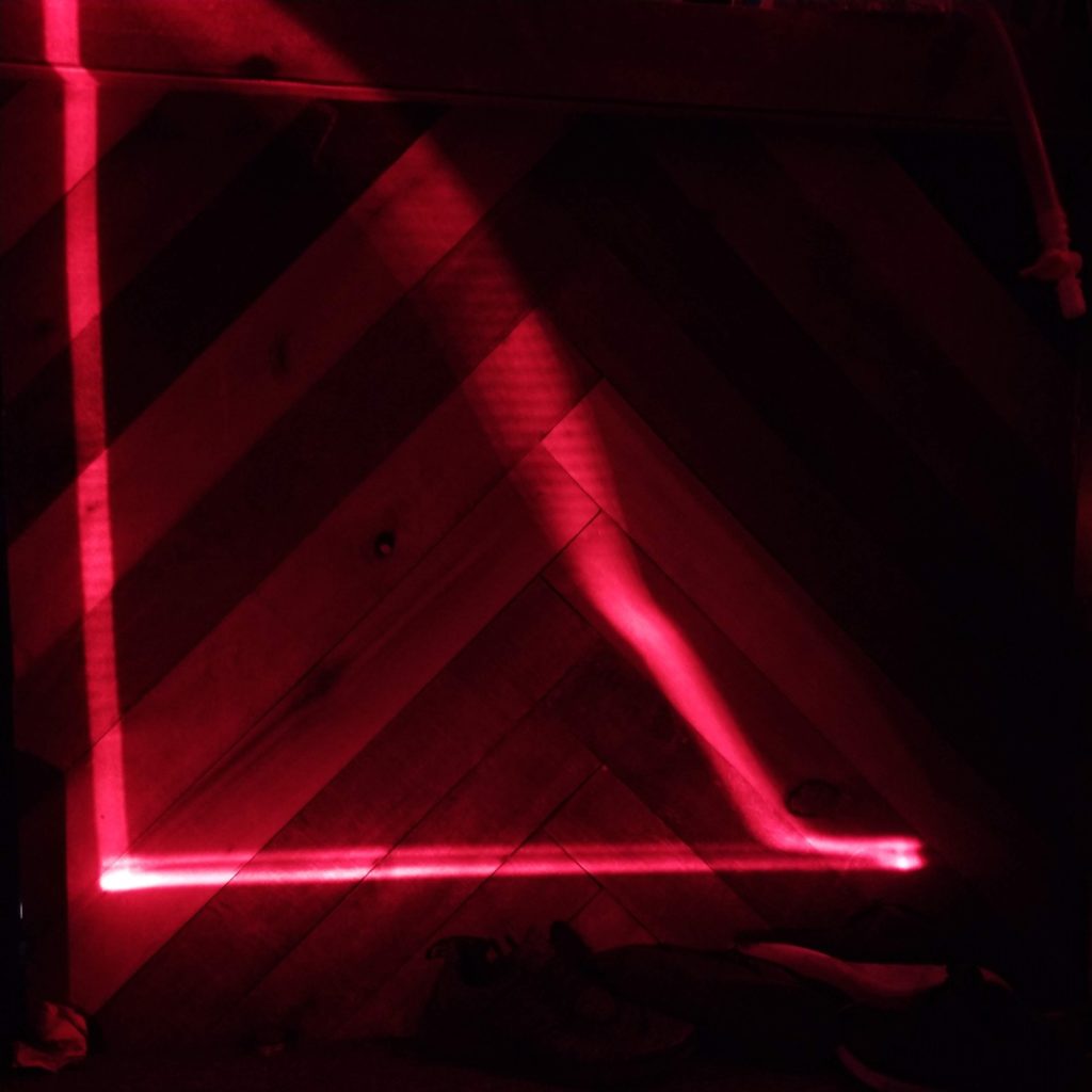
Right Triangle 
Square
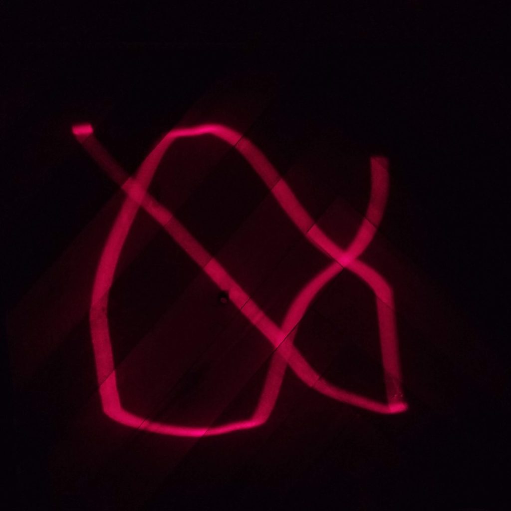
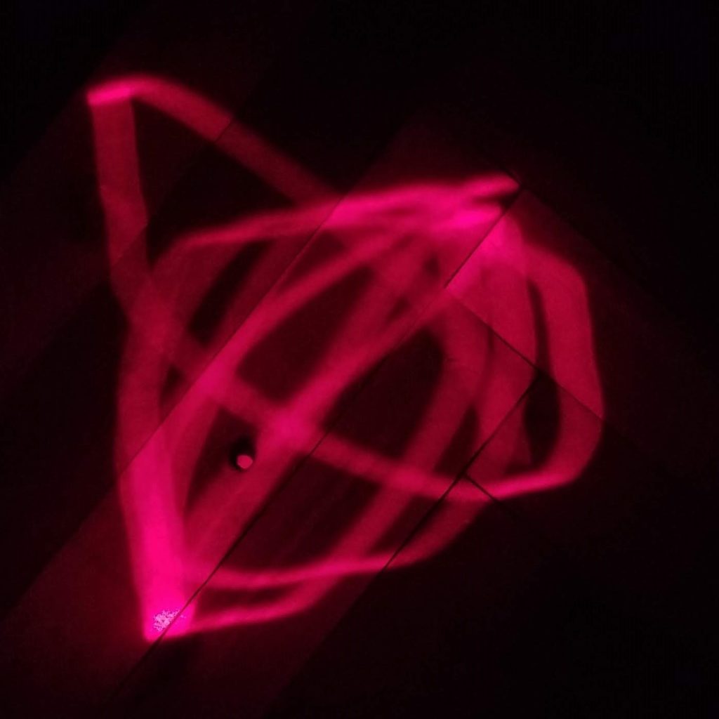
Below are more pictures of drawings created in the abstract shape mode.


The Code
#include
MiniMaestro maestro(Serial);

// PINS
const int xPotPin = 2;     //A1 = X-Pot input port
const int yPotPin = 1;     //A2 = Y-Pot input port
const int redPin = 3;      //Red Button Pin
const int greenPin = 2;    //Green Button Pin
const int laserPin = 4;

//X-axis Servo Variables
const int xServoMin = 6000; //5750;
const int xServoMax = 6750; //7000;

int xServoAngle = 0;
int xServoAnglePrev = 0;

//Y-axis Servo Variables
const int yServoMin = 6000;
const int yServoMax = 6750;

int yServoAngle = 0;
int yServoAnglePrev = 0;

//Pot Variables
int xPotValue = 0;
int yPotValue = 0;

//Push Buttons Variables
bool redVal = false;
bool greenVal = false;

//Laser Variables
bool laserOn = false;

//Geometric Shape Variables
int scaleX = 0;
int scaleY = 0;
int shape = 0;
int index = 0;
bool debounce = true;

int geometryIndex = 0;

bool upX = true;
bool upY = false;

int delayTime = 0;

void setup() {
  pinMode(redPin, INPUT);
  pinMode(greenPin, INPUT);
  pinMode(laserPin, OUTPUT);
  Serial.begin(115200);
}

void readValues() {
  // READ ALL INPUTS
  xPotValue = analogRead(xPotPin);
  yPotValue = analogRead(yPotPin);
  redVal = digitalRead(redPin);
  greenVal = digitalRead(greenPin);
  // Control Laser On or Off
  digitalWrite(laserPin, laserOn);
  //Record Previous Servo Angle Values
  xServoAnglePrev = xServoAngle;
  yServoAnglePrev = yServoAngle;
}

void calculateDelay() {
  delayTime = abs(xServoAngle - xServoAnglePrev) * 0.035;
}

void writeValues() {
  // Write to Servos
  calculateDelay();
  maestro.setTarget(0, xServoAngle);
  maestro.setTarget(1, yServoAngle);
  delay(delayTime);
}

// SHAPES
int lineX[] = {xServoMin, xServoMax};
int lineY[] = {6375, 6375};

int triangleX[] = {xServoMin, xServoMin, xServoMax};
int triangleY[] = {yServoMax, yServoMin, yServoMax};

int squareX[] = {xServoMin, xServoMin, xServoMax, xServoMax};
int squareY[] = {yServoMax, yServoMin, yServoMin, yServoMax};

int circleX[] = {6000, 6187, 6375, 6562, 6750, 6562, 6375, 6187};
int circleY[] = {6375, 6187, 6000, 6187, 6375, 6562, 6750, 6562};

const int threshold = 10;

void loop() {
  //Etch-a-sketch Mode
  while (redVal && !greenVal) { //Record Etch-a-sketch mode
    index = 0;
    while (redVal) {
      laserOn = true;
      readValues();
      // MAP POT RANGE TO SERVO INPUT RANGE
      xServoAngle = map(xPotValue, 1022, 0, xServoMin, xServoMax);
      yServoAngle = map(yPotValue, 0, 1022, yServoMin, yServoMax);
      writeValues();
    }
  }

  //Geometrical Shape Mode
  while (!redVal && greenVal) { //Play geometrical shapes
    xServoAngle = xServoMin;
    yServoAngle = yServoMax;
    while (greenVal) {
      laserOn = true;
      readValues();

      if (redVal && debounce) { //Debounce button press
        debounce = false;
        shape++;
        if (shape >= 4) {
          shape = 0;
        }
      } else if (!redVal && !debounce) {
        debounce = true;
      }

      if (shape == 0) {
        scaleX = map(xPotValue, 1022, 0, -20, 20);
        scaleY = map(yPotValue, 0, 1022, -20, 20);
        if (xServoAngle >= xServoMax) {
          upX = false;
        } else if (xServoAngle = yServoMax) {
          upY = false;
        } else if (yServoAngle <= yServoMin) {
          upY = true;
        }
        if (upX) {
          xServoAngle = xServoAngle + 10 + scaleX;
        }
        if (!upX) {
          xServoAngle = xServoAngle - 10 - scaleX;
        }
        if (upY) {
          yServoAngle = yServoAngle + 10 + scaleY;
        }
        if (!upY) {
          yServoAngle = yServoAngle - 10 - scaleY;
        }
        writeValues();
      } else if (shape == 1) {
        //Line
        for (int i = 0; i < 3; i++) {
          xServoAngle = lineX[i];
          yServoAngle = lineY[i];
          writeValues();
        }
      } else if (shape == 2) {
        //Triangle
        for (int i = 0; i < 4; i++) {
          xServoAngle = triangleX[i];
          yServoAngle = triangleY[i];
          writeValues();
        }
      } else if (shape == 3) {
        //Square
        for (int i = 0; i < 5; i++) {
          xServoAngle = squareX[i];
          yServoAngle = squareY[i];
          writeValues();
        }
      } else if (shape == 4) {
        //Circle
        for (int i = 0; i < 8; i++) {
          xServoAngle = circleX[i];
          yServoAngle = circleY[i];
          writeValues();
        }
      }
    }
  }

  laserOn = false;
  readValues();
  xServoAngle = 6375;
  yServoAngle = 6375;
  writeValues();
}
I used the Pololu Mini Maestro library for controlling the servos: https://github.com/pololu/maestro-arduino
Special thanks to Zachary Berry for helping me with some coding issues that I faced.