When this class first started, I was intimidated by the amount of freedom we had with creating what we wanted. But I was soon inspired by what I’ve been calling a perspective piece. A perspective piece is one where there is one image on one side, and when rotated 90 degrees, it makes another image. Below are photos of an example I found that was made with guns.

One side of the piece. 
The other side of the piece once rotated 90 degrees.
I enjoyed how this piece of art worked to raise awareness about the gun control problem the United States is currently facing. I wanted my project to shed light on a problem as well. I chose to focus on ocean pollution because I really enjoy the ocean and am passionate about improving its quality. Therefore, I chose to have my images be a wave and a trashcan. Before I was able to plan out exactly what the images were going to look like, I had to plan how I was going to do it. Using cardboard and string I had around my house, I created a small model of what I was hoping to create.

With this idea of how I was going to execute my plan in mind, I started designing the images I was going to make. The framework I created was a cube made with 12 1-foot long PVC pipes, corner pipe fittings and a 1-foot by 1-foot pegboard suspended in the center. In order to come up with a plan, and ensure this was a feasible idea, I modeled the framework and the LEDs I was using in SolidWorks. I modeled the images that I wanted to create in an assembly on SolidWorks, then took measurements of how far from the top pegboard the bulb needed to be. In addition, I marked which hole in the pegboard the bulb needed to come out of to make sure I would get the image I wanted.
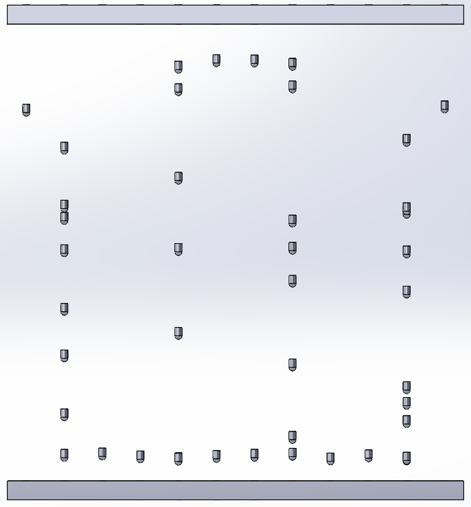
The image of the trashcan I modeled in SolidWorks. 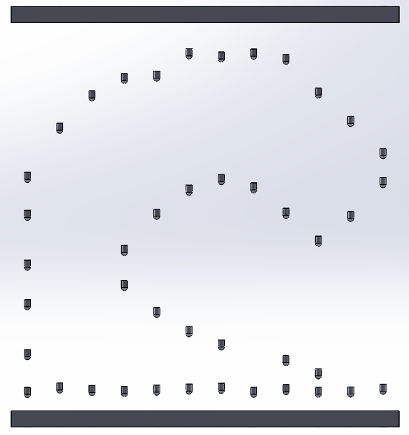
The image of the wave I modeled in SolidWorks.
Once the plan was made, it was time to solder all of the LEDs together. The images consisted of 42 LEDs soldered in parallel. Once all the LEDs were soldered together, the positive and negative leads needed to be soldered together so there was only one wire for the positive connections and one wire for the negative connections to be put into the power source. All of the solderings were done on top of the pegboard. To cover all the wires and soldering connections, I glued a piece of dark fabric to the PVC pipes at the top. This also gave the project a more polished look. The picture below is the first iteration of the project.
While I was happy with this image, and getting all of the wires working properly, the LEDs didn’t look polished. In an attempt to straighten the wires to make the images more clear, I attached pieces of “invisible wire” to the LEDs, pulled the wires straight down as much as possible, and connected them to their corresponding holes at the bottom of the pegboard. However, the “invisible wire” was quite visible and did not look very clean. Therefore, I made the decision to remove the wire and let the LEDs hang freely. In turn, the images became a little bit more abstract, but I enjoyed the look that way. Because there was no need for the pegboard at the bottom anymore, I removed it and covered the bottom with dark fabric to eliminate as much light reflection as possible.
For the final documentation of my project, I created a short video to represent a viewer walking from one side of the project to the other. This will allow viewers to see both images, and how they are created by the same piece of art. The video can be found below.
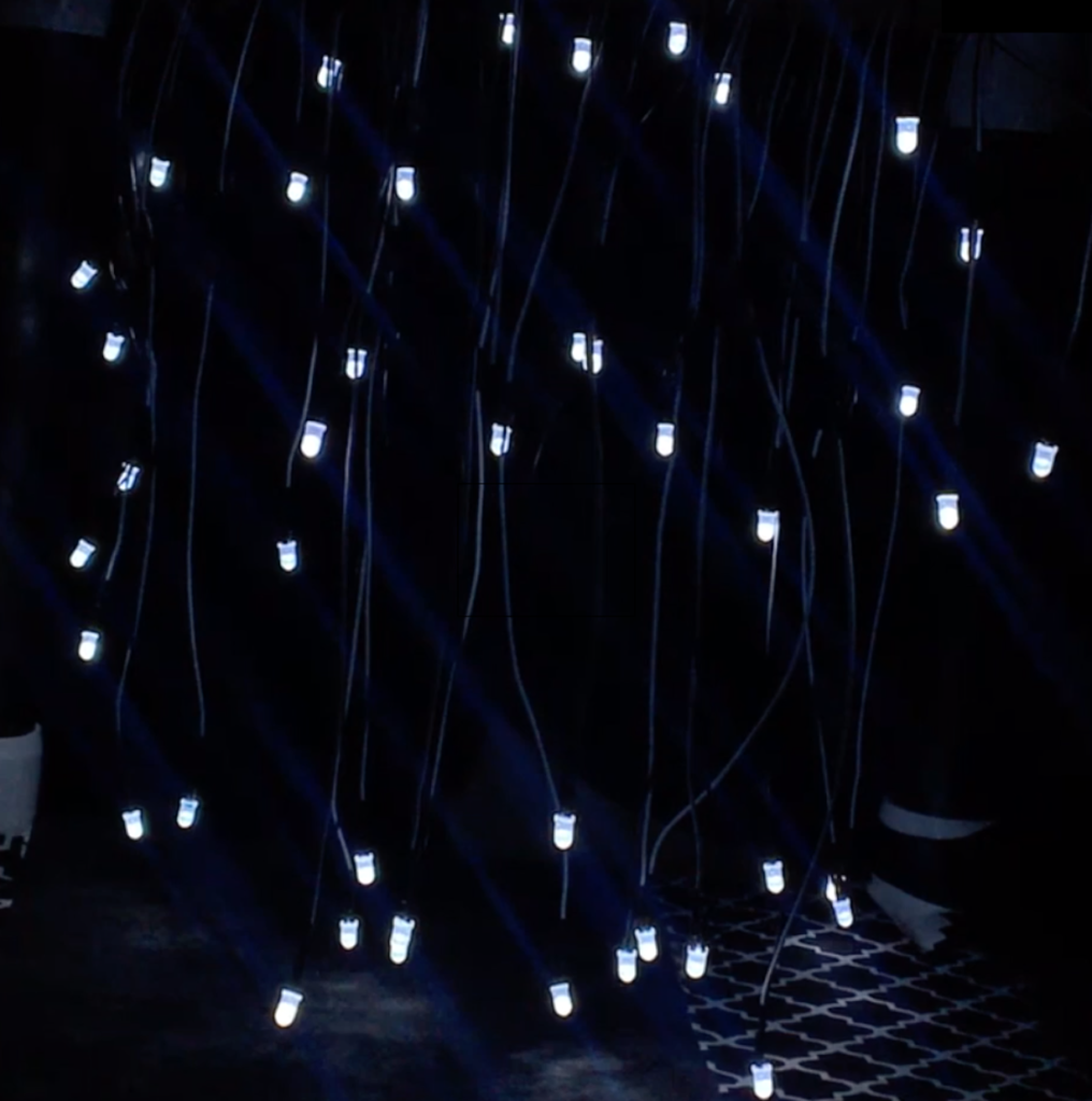
The final wave design made with LEDs. 
The final trashcan design made with LEDs.
All in all, I am very proud of the piece of art I have created, and appreciate all the helpful hints and words of affirmation received by my professor and classmates over the course of the term.