Robot Arm Light Painting – Final Documentation

Zachary Armsby

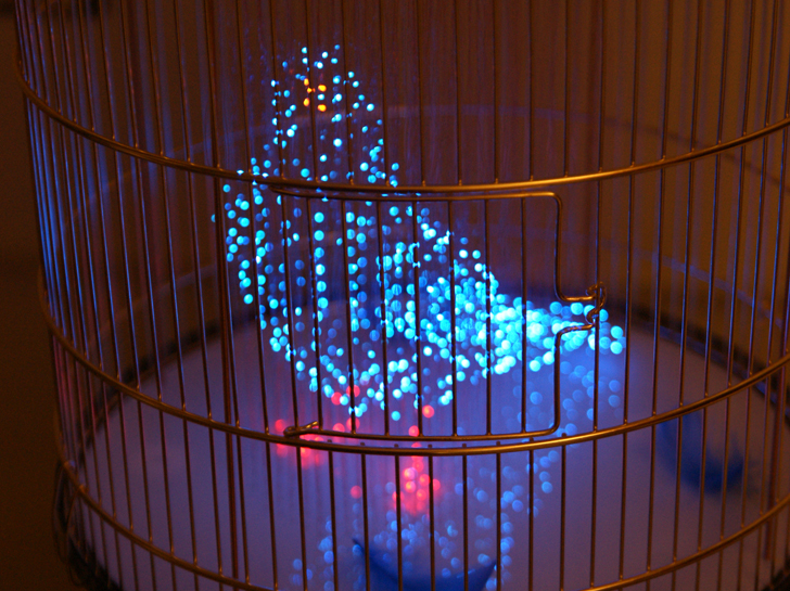
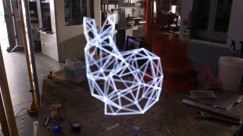
For my project I chose to make light painting video and pictures using a robot arm. While I was looking for ideas at the beginning I saw lots of light paintings with organic and hand drawn lines, only a handful used sharp and precise lines. With my background in robotics and computer science I decided to use a robot arm to draw precise geometric images with light. After thinking about my initial idea for a while I realized two key things. First, the long exposure photo would only capture a 2D image while the arm was moving in 3D. A single photo would only capture a projection of the complete form. Second, that the ABB arm in Washburn was able to precisely replicate a motion path. In order to capture the form of the 3D drawing I could replicate the same path multiple times and move the position of the camera around the arm and stitch all of the photos into a video. This would fully show the 3D form.

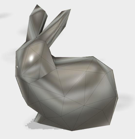
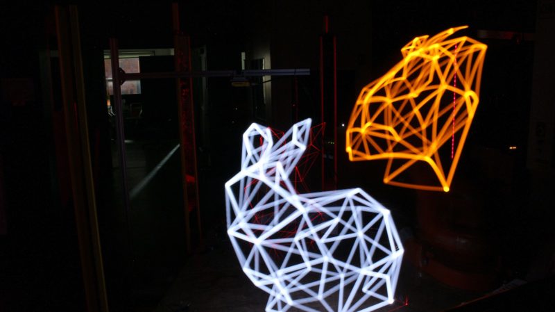
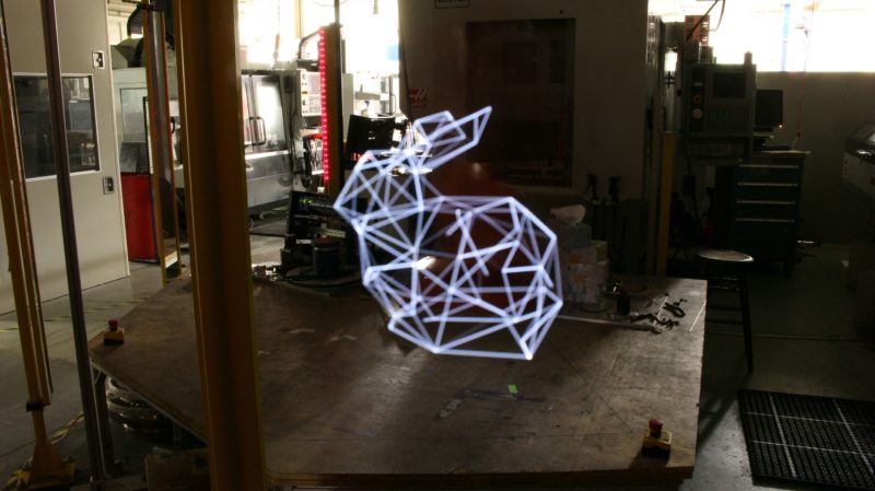
The form I chose to draw was a low poly bunny, the model was originally the Stanford Bunny, a 3D file used to test 3D printer quality. I decimated the model to be low poly and still retain distinctive features.

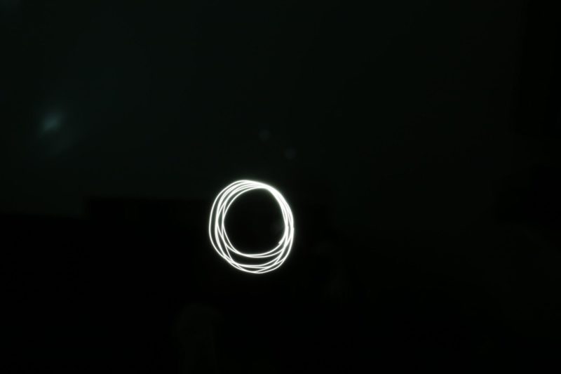
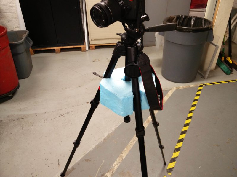
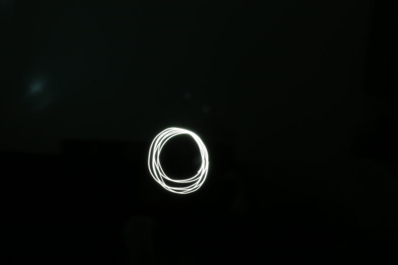
Then I learned how to light paint. To accomplish this I checked out a tripod and DSLR camera from the ATC and had my friend draw a circle with his phone’s LED light. I used this to learn how to adjust the camera settings for a long exposure photo.

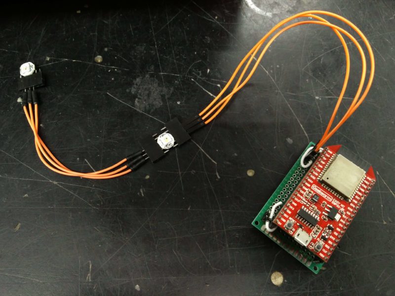
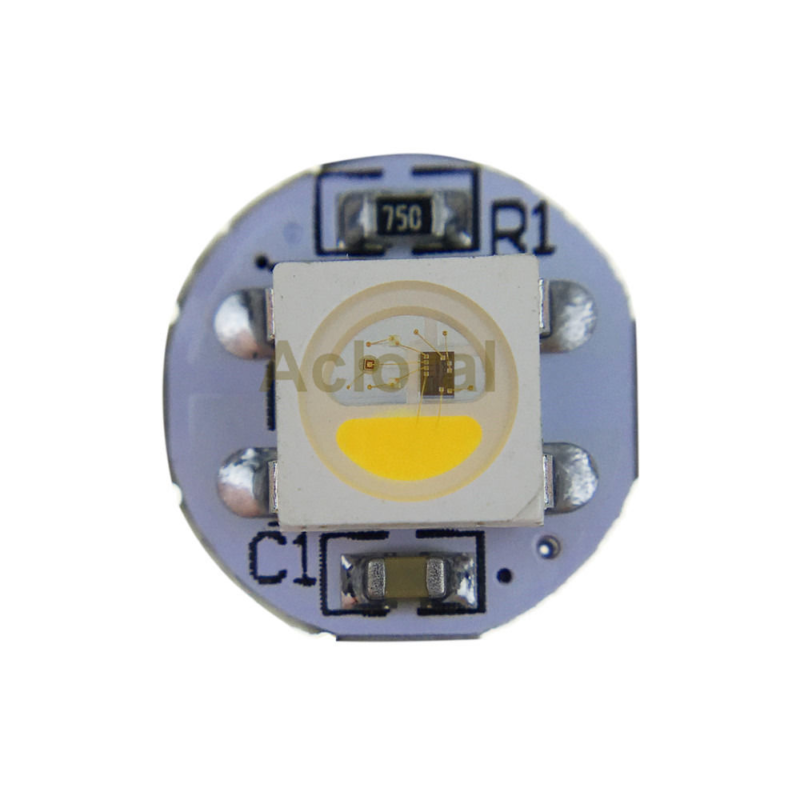
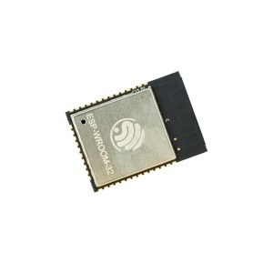
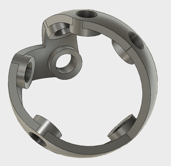
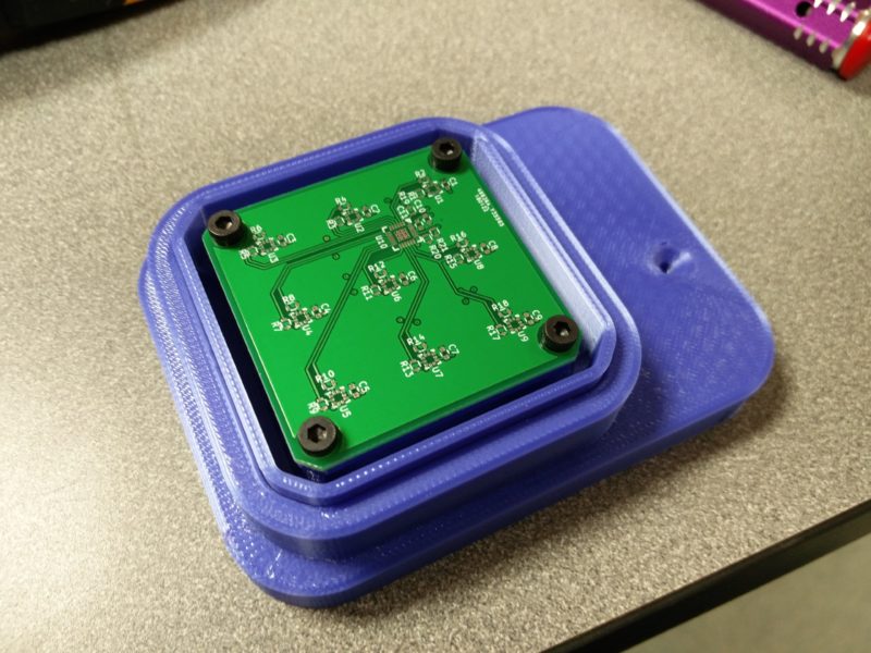
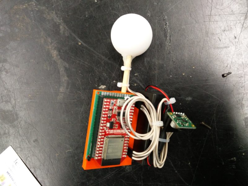
Next I made a light source to attach to the robot arm. I did this by 3D printing a mount for all of the electrical components; an esp32, battery, and controllable LED. The LED was attached on the end of a dowel and placed inside of a small ping pong ball cut in half with nichrome wire. This was all attached with hotglue. Every part was designed to withstand the large amount of acceleration and jerk it would experience on the end of the robot arm.

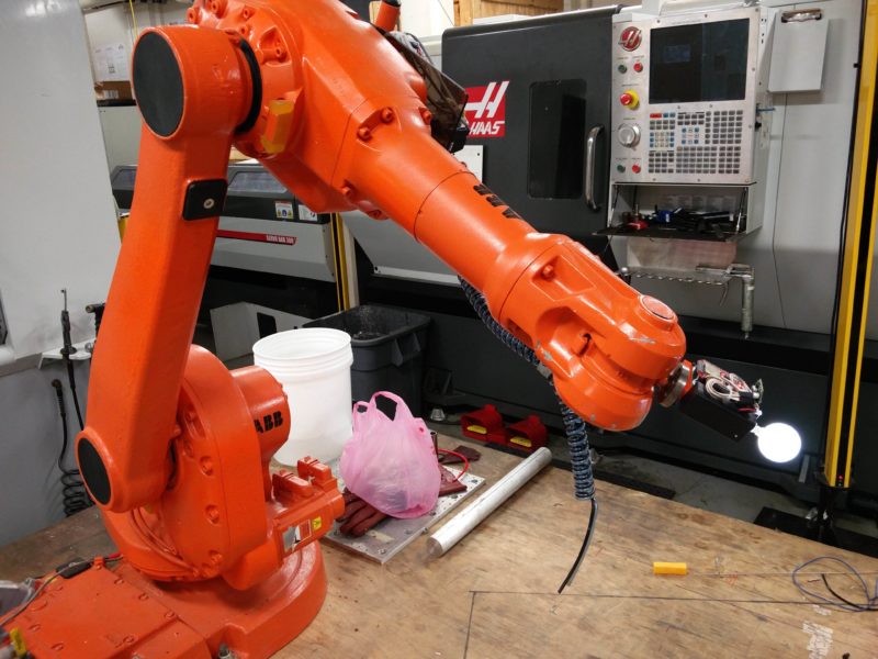
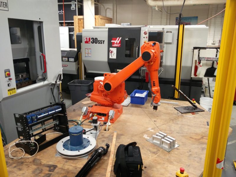
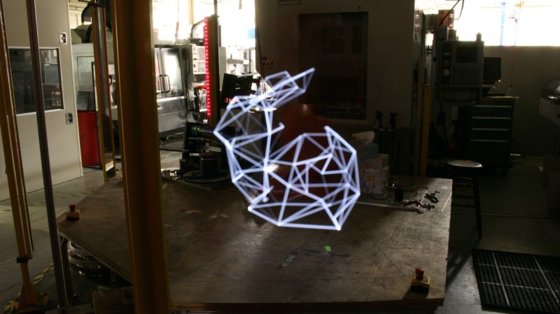
After completing the construction of the light source and learning how to light paint it was time make a light painting with the arm. This required learning how to use robotstudio, the software used to control the arm. Using the edge path generation feature I was able to trace the 3D shape I wanted. Then I had to reorient all of the target points to prevent the arm from blocking the light and to make sure every point was reachable. After this I learned how to load a program onto the arm and operate the controller. At this point I was able to make a light painting.

Then I switch tasks to focus on the 3D and rotation elements of the project. In order to move the camera in an arc around the arm  it was necessary to make some custom tools. First, to stabilize the tripod from the ATC I cut a piece of foam to extend the legs a constant amount while re-positioning the camera.

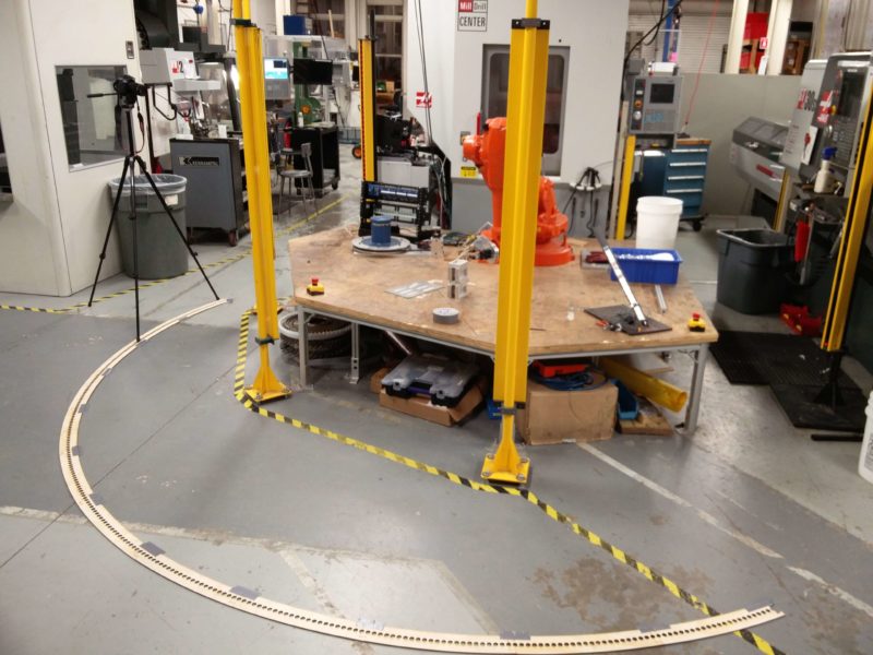
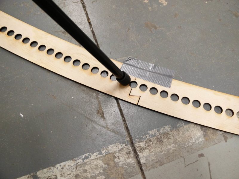
Next I made a track of circles in an arc that slot together so the tripod feet could be positioned fast and accurately. The track was positioned so the center of the drawing would be at the center of the arc.

To test the rotation video component I took 231 regular photos around the robot arm. After taking all of the photos I learned how to use Adobe Premier to stitch all of the photos together.

Despite all of the fixtures, the video was shaky. To correct this I used a warp stabilizer effect to stabilize the video.

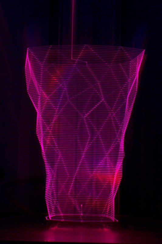
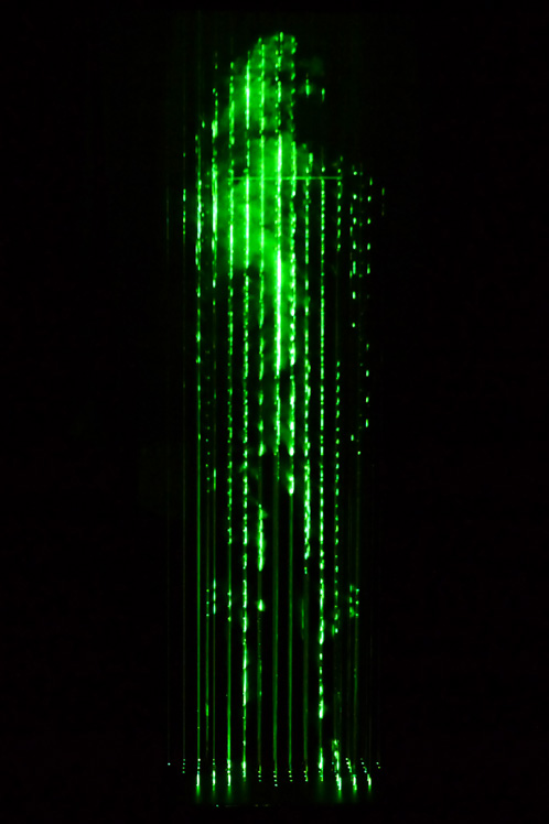
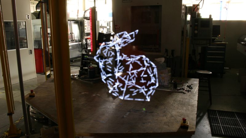
At this point all of the basic techniques where tested and it was time to make the final products. To make the video I needed to take 231, 77 second, long exposure photos; this took about 8 hours. A portion of one of the long exposures is shown below.

After taking the photos they where stitched together.

Then stabilized for the final rotation video.

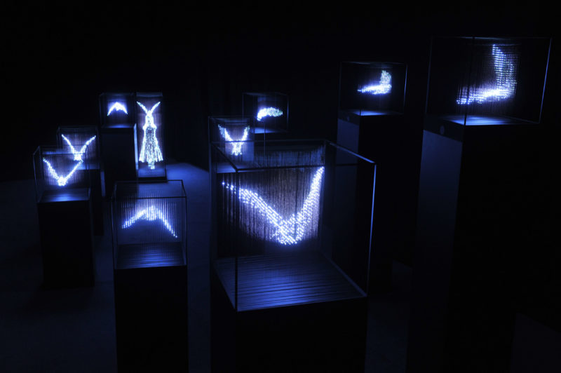
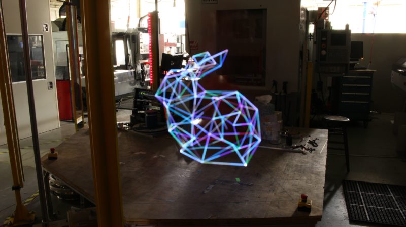
After the rotation process I experimented with other techniques to try to improve on the solid white line. These photos are discussed in the Polish & present blog post.

Over all I am very happy with the execution and final results of my project. Previous posts explain the full iteration process.

Polish & Present

Last week I made a rotating light-painting video by keeping the RGBW LED on the arm constantly on, only having the W component active.

This week I altered the behavior of the LED and tested different lighting patterns from the same perspective. First I tested blinking the LED on and off at a constant rate to see how only a partial image compared to the full image. Initially the LED was set to blink every 1 sec.

While the original image is still visible the large number of separate lines makes the image look very busy and messy. To change that effect I increased the blink time to 2 sec.

Then I increased the blink time to 4 sec.

Then I increased the blink time to 10 sec.

The original image is still discernible but the the new image is less complicated with simple lines that don’t completely connect. This style with less lines and connections is more abstract and less ridged while still remaining geometric due to the the straight lines and harsh angles.

Next I tried slowly increasing the brightness of  LED repeatedly in various cycle times to see if a slow fade in could soften the harsh beginning of the lines. Initially I tried a cycle time of 2.55 seconds.

Compared to the blinking image with a cycle time of 2 sec, this image seems to have softer transitions into the lines. I then tried a cycle time of 6.5025 sec.

Then I tried a cycle time of 25.5 sec.

As the cycle time increase some parts of the image become brighter than others highlighting different parts of the image rather than having a single brightness.

Lastly, I tried changing the color of the LED using the RGB components of the LED by randomly setting each component every 1 sec.

The color was able to add more dimension to the image, but a less random approach could improve it further and add focus to different parts of image. 

Everything Working

My project is to make a rotating light painting with with a robot arm, and every thing works. This week I had the arm draw a low poly bunny again in auto mode after getting permission from professor Putnam. The video below is the robot moving in real-time in auto mode on low speed.

After drawing the pattern again in auto mode I tested illuminating the background of the shop and ran the program at different speeds to see how the increased light level would affect the brightness of the background and the light streaks.

After experimenting with the program speed I decided to run at 50% speed for the rest of the light paintings so the environment would be visible, but not compete with the light streaks for attention. Next, I tested the rotation aspect of the project by stitching together and stabilizing a series of long exposures while re-positioning the camera in an arc sequentially. This was done to verify that this method for creating a video, used before on the regular photos, still worked for light paintings. The same rendering process worked and the result can be seen below.

After verifying that the technique for combining images into a stabilized video still worked I expanded the experiment into the full art piece.  After 6 hours of taking long exposure photos every 77 seconds the final light painting rotation is shown in the video below.

The final piece is able to make use of the 3D drawing motion of the arm by showing the series of long exposure photos of the exact same motion produced by the robot arm. However there is room for improvement, the program could be reworked to remove the flicker at the start of the path by having a brief overlap, the process of the generating the program could be automated, and the the tripod movement could by automated. Overall I am happy with the progress on this project.

Failure, Recalibration & Iteration

My project is making a light painting with a robot arm . This week went well and I got a lot of stuff working, but some things need improvement. First I finished making the end effector for the robot arm, along with 2 different sized lights to put on the end of it.

Then after writing the program to control the arm and move in a pattern I attached the end effector to arm tested it out in a light painting. Below is a still picture of the arm and below that the light painting is shown.


Overall the painting turned out very nice, however there are some improvements I need to make. I need to cover orange and red status lights on the ABB arm and the esp32, roll down the shades for the window in the background, and better center the frame. Otherwise I am happy with the progress so far.

Maquette

My project is using the ABB arm to light paint a shape in 3D. For my maquette I made a few proof of concept photos/videos. The first element of the project I tested was the light painting. To test this I checkout a DSLR camera and tripod from the ATC and experimented with the settings for a long exposure photo to make a light painting. In the photo below I had a friend move their phone in a circle in a dark room.

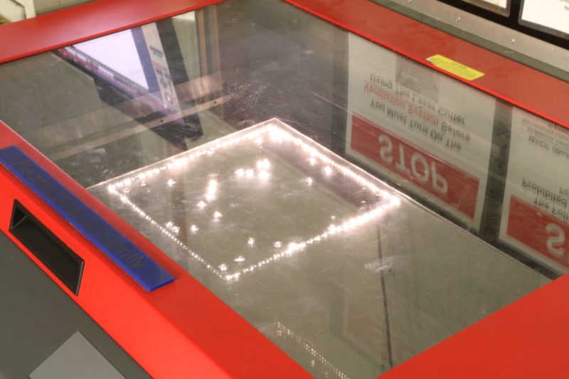
 I had an opportunity to test this element again when a was waiting to laser cut another part of the project. The laser itself was not visible until it burned through the material being cut. This long exposure photo did not turn out as well as the previous one due to the ambient light in the shop.

After that I tested the time-lapse element of my project. Since light painting is constrained to 2D it is necessary to take multiple pictures of the same scene to show the 3D motion of the robot arm. To prototype this element of my project I laser cut a jig for a camera tripod to rotate in an arc around the arm. In the photo below the setup is shown with the jig on the floor around the ABB platform in Washburn.

Each of the holes in the jig is a position for a photo to be taken, where the tripod’s legs are aligned.

After taking 231 photos with the jig I learned how to use adobe premier and converted all of the photos into a video shown below.

Despite making a jig the video was very unstable from slight misalignment. However this was able to be fixed with a stabilizer in post processing, the result is shown below.

The last element I worked on was the lighting system. For this I hooked up a few sk6812 LEDs to an esp32, made a driver for them, and made a protoboard to attach to the ABB arm.

Bill of Materials:

  • small ping pong balls to defuse the LEDs ($4) (do not have)
  • plywood for laser cutter ($9)
  • esp32 ($5)
  • wire ($1)
  • LEDs($5)
  • DSLR camera from ATC (free to use)
  • tripod from ATC (free to use)
  • ABB arm in Washburn (free to use)

Schedule:

(4/5) – test light painting, rotation timelapse prototype, control LEDs

(4/12) – finish light fixture, control ABB arm, test light painting with arm

(4/19) – complete first light painting video

(4/26) – iterate light painting video

Concept Proposals – Zachary Armsby

Concept 1 – Self Supporting Large LED Sculpture

The first project concept that I would like to propose for my final project is inspired by the light sculptures of Makoto Tojiki and Jun Ong (displayed below). Both of their works are a form of light sculpture, using light emitting elements to define a form. The use of light emitting elements makes the sculptures stand out more and make piece more impactful.

For my project I propose making an LED sculpture, composed of nodes with LEDs housed in a 3D printed support structure inside of ping pong balls connected  by bamboo skewers. The support structures would be generated with a script from a low poly stl model, designed to fit inside ping pong balls and have bamboo skewers slot in. The ping pong balls would diffuse the LED’s light. Each of the LEDs would be controllable with a 1-wire interface and have power and ground run to each node.

To test the concept I made a script to generate the support structures for the nodes. Starting with a stl mesh it outputs all of the necessary support structures for the sculpture. Below the starting stl and output support structures are shown.

Concept 2 – Light Painting with Robot Arm

The second project concept that I would like to propose for my final project is inspired by the light sculptures of Autodesk Pier 9, University of Michigan, and Gianluca Pugliese  (displayed below). All of their works use a form of light painting with CNC control to create their pieces, resulting in geometric lines and precise control over the final result.

For my project I propose using the ABB arm in Washburn to make a light painting video of a mesh while rotating the position of the camera around the arm drawing to see the 3D motion of the arm and the machine shop in the background. This would be done by attaching an LED to the ABB arm and taking a lot of long exposure pictures around the arm to make video frames.

To test the concept I got an introduction to the ABB arm, took a test long exposure photo of my friend drawing a circle, and tried making a panoramic time lapse video.

Makoto Tojiki

Makoto Tojiki is a Japanese light artist in Chiba, Japan who primarily works with LED sculptures. Tojiki studied industrial design and then worked as an in house designer. After that he became a full time artist starting in 2003. Tojiki is best known for his technique and style of vertical LED strands that are selectively placed to create a 3D shell of an object. His most popular series “No Shadow” makes use of this technique. Shown below are some pieces in the “No Shadow” series.

Tojiki has stated that he is interested in perception and how the memory of different perceptions of the same object conflict with new observations of the object. In the “No Shadow” series as the viewer walks around the piece the perceived  3D surfaces in the work change and give more tangible and fulfilling sense. Additionally the perspective changes different parts of the sculpture are highlighted where the LEDs overlap more, creating a sense of shadow with only light.

No Shadow – Cellist
No Shadow – Horse with no Shadow
No Shadow – Hope and Dream

Tokiji has also used other techniques, such as shining lasers in mist in his work “man in the rain”. This approach causes the piece to change form as the mist moves and reflects the lasers differently. From a stationary point of view the perception of the piece changes. This constant change makes it difficult to define the form of the sculpture.

man in the rain

Another technique Tojiki has used is binding optical fibers with resin to make a sculpture. In his piece “no title” there are two sculptures of a person in white and black optical fiber were there are sections from each sculpture missing. However the other sculpture, when aligned right, is a compliment of the other sculpture and together form a whole. By defining light and shadow with two complementing sculptures Tojiki is able to explore how light and shadow interact to define a single form.

no title


Introduction and Art Portfolio – Zachary Armsby

My name is Zachary Armsby, I am a senior CS and RBE student. I have a very technical background with electronics (soldering, circuit design), computer (programming), and manufacturing skills (3D printing, laser cutting, milling, machine tools). Most of the design work I have done has required 3D modeling and printing. When designing a part the overall ascetic design has a large impact on how people perceive the part. I have previously made a few art projects and have taken art classes at WPI (AR1101, AR2101, AR2201, and AR3200). I primarily like to create art projects that have a physical presence and are geometric. The three dimensional aspect gives the piece a more tangible feel and helps to make more of an impact.  Below are some of the projects I have made.

While learning how to weld I made two sculptures out of scrap metal. I found simple shapes of scrap and welded them together to make a cat and a penguin.

In 3D modeling class I made a model of a Zergling from Starcraft because it had a lot of interesting organic shapes that where interesting to study and make.

For a project in interactive art I made an abstract partial mesh of a bunny and had it rotate in place. The mesh only had a random third of all of the triangles but was still able to represent the original model well as it rotated.

As a personal project I experimented with the API for Autodesk’s Fusion CAD package. I tried to reconstruct a mesh (same mesh as above) into a solid object that could be made from small parts into a large object.

As a part of my MQP I had to cast urethane into a part. I had to experiment a lot with the design and liked the tactile aspect of the part.