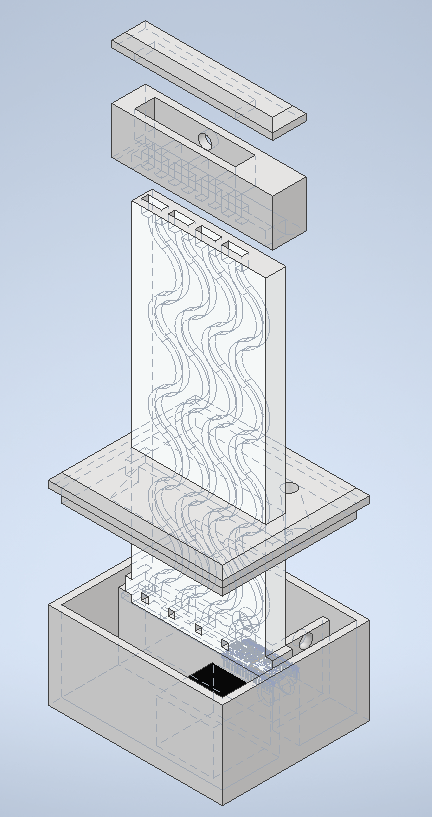
I was hoping to get some of my materials in time to have something more physical for the maquette, but they only just arrived about 20 minutes before class. Instead, the bulk of my maquette is in the form of a more detailed CAD model. I plan to 3D print and laser cut the pieces soon so I can find oversights and weak areas to address in later iterations.
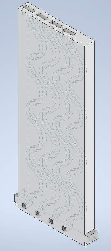
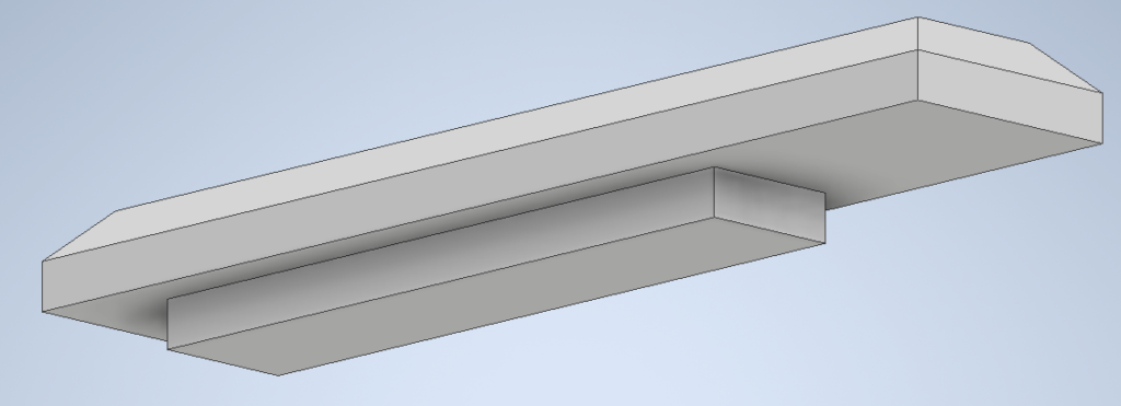
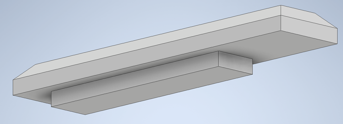
In the bottom box, there is room for the water and electronics, separated by a wall. On top of the wall is a channel for an LED strip to sit, and the acrylic panels sit directly on top. The panels and have been changed to spit the water out of the side instead of downwards, in order to allow the LEDs to be right up against the acrylic. There are also some holes for routing wires/pipes, and a separate lid piece locks the panels in place.
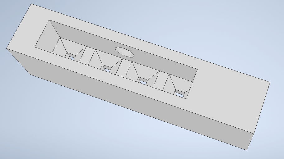
The top piece is still a work in progress. Currently it just has a hole for a pipe which goes into a chamber with four funnels. This may change in the future if I decide to have LEDs on both the top and bottom, since I would want the LEDs to be right up against the acrylic (like in the bottom).
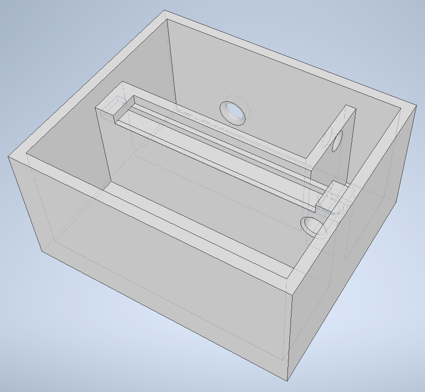
Bottom box 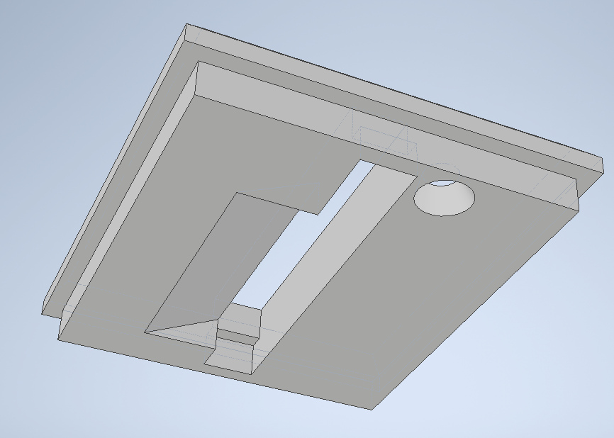

While I didn’t get my main materials in time for the maquette, I still wanted to make a to-scale model of it , so I made a terrible cardboard mock up just to see how I liked the size of it. In general, I like the scale, though I wish I could make the base of it less thick front to back. I might be able to shave off a half inch or so to depending on how I mount the pump. There’s also a chance I make it slightly wider to accommodate an extra channel in the acrylic, though it wouldn’t add more than an inch or so to the width.
Supply List
- ESP32
- 12V 4.8W DC Water Pump (3m head)
- Tubing (5/16″ ID x 7/16″ OD to match pump)
- 12V 2.5A DC power supply
- 12V to 5V buck converter (need 5V to power the ESP32 and LEDs)
- MOSFET (to control the 12V water pump power with a 3.3V signal from the ESP32)
- Waterproof 144/m addressable LED strip
- 1/4″ acrylic
- Each of the 3 layers is 5.5″ x 13″ so a nice 18″ x 24″ sheet should be good, with some extra room for mistakes.
- Something to glue the acrylic layers together (will likely use Weldon #4)
- Useful resource: http://www.daniellewethington.com/gluingacrylic/
- 3D printing will be done at the makerspace most likely
- On/off switch
- Maybe a button or two (could use for different modes or something)
- Maybe an encoder or potentiometer (brightness control?)
Schedule
Week of 9/13
- Order supplies
- Finish CAD model first pass
- Get some parts printing at the makerspace
- Experiment with electronics
- Experiment with acrylic adhesive
Week of 9/20
- Laser cut acrylic
- Test assembly to see how everything fits
- If it goes well, glue the acrylic sheets together and make sure it’s still good
- Edit CAD model to fix problems & reprint at makerspace
Week of 9/27
- Second laser cut acrylic attempt (if needed)
- Second pass of assembly
- Write final code for sensors and effects
- If necessary, start third/final 3D print
Week of 10/4
- Final assembly
- Polish + finishing touches
Buffer time
When you bond the acrylic sheets to each other, are you going to trim down each side if there is an overhang? I wonder if you could put the sheets in the laser cutter afterwards to trim each edge and give it the polished look.
I’m excited to see how you move forward with this! This is definitely a tricky design with some nuance. You have a very detailed timeline and I’m sure you’ll do great if you stick to it. I’m glad you kept it on the thin side and respect your commitment to the waterfall concept by thinking of other ways to return the water.
This is such a cool concept! Do you foresee any water leakage issues between the acrylic panes? And if so, how will you fix that issue?
For adhering the acrylic layers together you could use acrylic cement, like Weld-on 4, it would definitely be water tight, although I’d definitely test some scrap pieces to see if bubbles can form.
Nice progress so far, the model really helps communicate what you’re going for!
I think your best bet for getting water to the top would be 1 or 2 black pipes running on either side of the acrylic box, rather than in the back. That way you could hide whatever tube is needed to pump the water, without it being visually out of place (it would just look like structural parts of the frame).
I had an idea regarding the electronic storage and the water at the base of the piece. What if you used pure/ distilled water, It would cause less damage if it were to leak into the electrical components. Also I had an idea for the returning of water to the top you could add two cylindrical pipes on each side of rectangle, like columns, for the water to go back up. i just saw matts comment, i wonder how it would look if it was clear, and if you make it colored it could be the same color as the base.