Maquette

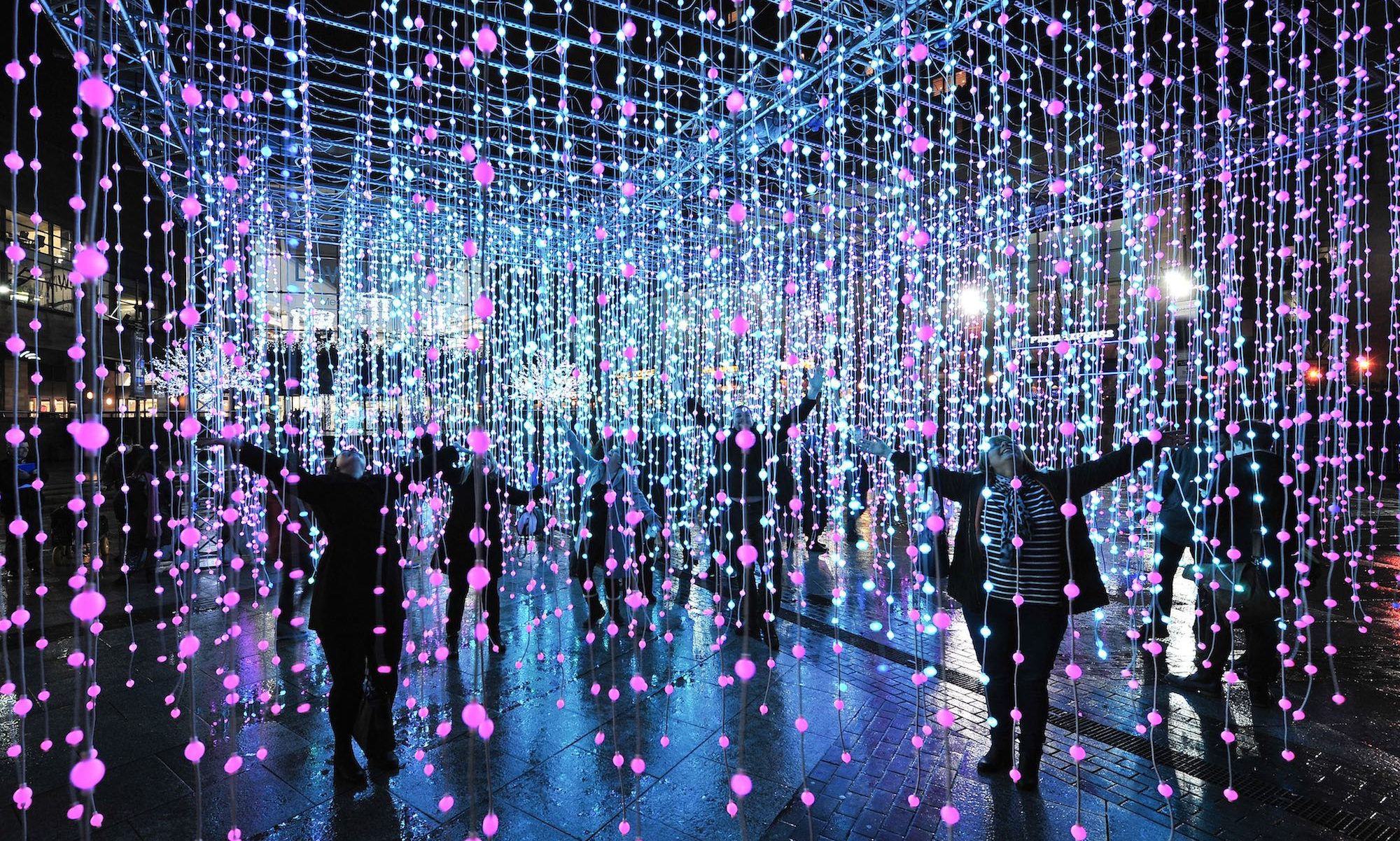
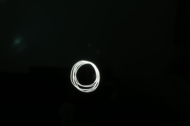
My project is using the ABB arm to light paint a shape in 3D. For my maquette I made a few proof of concept photos/videos. The first element of the project I tested was the light painting. To test this I checkout a DSLR camera and tripod from the ATC and experimented with the settings for a long exposure photo to make a light painting. In the photo below I had a friend move their phone in a circle in a dark room.

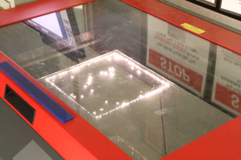
 I had an opportunity to test this element again when a was waiting to laser cut another part of the project. The laser itself was not visible until it burned through the material being cut. This long exposure photo did not turn out as well as the previous one due to the ambient light in the shop.

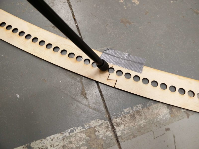
After that I tested the time-lapse element of my project. Since light painting is constrained to 2D it is necessary to take multiple pictures of the same scene to show the 3D motion of the robot arm. To prototype this element of my project I laser cut a jig for a camera tripod to rotate in an arc around the arm. In the photo below the setup is shown with the jig on the floor around the ABB platform in Washburn.

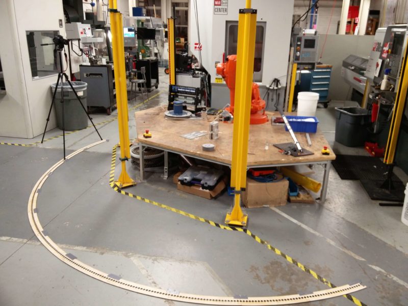
Each of the holes in the jig is a position for a photo to be taken, where the tripod’s legs are aligned.

After taking 231 photos with the jig I learned how to use adobe premier and converted all of the photos into a video shown below.

Despite making a jig the video was very unstable from slight misalignment. However this was able to be fixed with a stabilizer in post processing, the result is shown below.

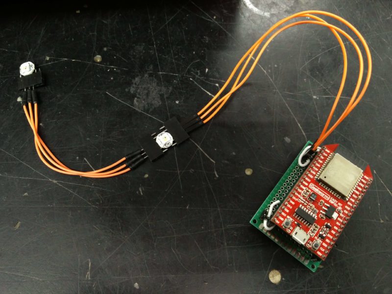
The last element I worked on was the lighting system. For this I hooked up a few sk6812 LEDs to an esp32, made a driver for them, and made a protoboard to attach to the ABB arm.

Bill of Materials:

  • small ping pong balls to defuse the LEDs ($4) (do not have)
  • plywood for laser cutter ($9)
  • esp32 ($5)
  • wire ($1)
  • LEDs($5)
  • DSLR camera from ATC (free to use)
  • tripod from ATC (free to use)
  • ABB arm in Washburn (free to use)

Schedule:

(4/5) – test light painting, rotation timelapse prototype, control LEDs

(4/12) – finish light fixture, control ABB arm, test light painting with arm

(4/19) – complete first light painting video

(4/26) – iterate light painting video

Yeasty Light Art Prototype

Hello all!

This week, I was tasked with making a yeast light art prototype. I decided to explore the painting technique this week, as this is a more sure bet than the long exposure, photographic technique.

Show and Tell

Because my project uses genetically modified GFP yeast, I cannot transport it to class. I am, however, meeting with Professor Farny tomorrow- she has a lab facility in Goddard that can handle my yeast plates. I may be able to get the class access to the Goddard Lab to see the final work.

Instead of the show and tell, I documented my process & results.

To make my GFP Yeast Prototype, I first grew green florescent yeast in a liquid medium.  I also grew non-GFP yeast in another tube.

After that, I selected a petri dish with yeast-agar inside of it, and pipetted both yeast solutions into the dish. I did so randomly, so the yeast could grow as they pleased. I mixed the yeast strains so that they could grow together and compete for space on the dish, naturally producing complex patterns in the process.

This is the dish @ 0 hours:

The dish @ 1 day:

After the yeast grew, I contacted Professor Duffy & he let me use his microscope to take pictures of my plate.

The microscope is fitted with different light filters, to allow visualization of GFP (green) , BFP (blue), and mCHERRY (red). I took my sample, placed it under the microscope, and turned on the GFP filter (UV/395nm wavelength).

This was the result:

The glowing portion is a GFP cell cluster that grew.

This picture was taken at 8X, so it is a portion of the plate. Also, the microscope camera was acting up, so I had to line my phone up to the ocular to take the picture,which is why the picture has a low resolution.

Optimization:

There are several optimizations I would like to do for my yeast art:

  1. Find a microscope/ system to allow imaging of the whole plate
  2. Use paint brushes to make designs on Agar plates
  3. Get a camera to take a picture of my plates every minute for 12 hours…
  4. Use my new long exposure setup to make glowing yeast photography

As for (1), I have also contacted Professor Farny; I heard from Professor Duffy that her IGEM team makes bacteria art on agar plates as well, and has a setup that will allow for full plate illumination. I will be able to do this on Friday.

I am also going to try exposing my plates to simple LEDs of the correct wavelengths, to see if this is an effective means of art visualization. If that works, I may be able to bring my art to class.

Simple LED setup I rigged with a basic stamp

*I will also purchase a UV (395nm) flashlight to visualize the GFP.


This is an image I took with my LED setup. I currently am waiting for a UV LED to get delivered to illuminate the GFP, but the effect produced with the backlit red LED is still  visually interesting.


I have also made progress with my UV long-exposure setup:

This is a UV sterilizing light-bulb, placed in a simple desk lamp, underneath a protective box. Yesterday, when the parts came in, I made a plate of GFP yeast, and exposed it to the light for about 5 hours. I am currently awaiting results.


Materials:

I have acquired most of the materials I need:

  1. GFP Microbes
  2. Petri Dishes
  3. Cell Feed/Agar
  4. Basic GFP Microscope
  5. UV Lamp
  6. Transparent Printing Sheets
  7. Box

I still need these materials/accesses:

  1. LED Lights/ Illumination Visual tool (I have ordered this)- http://https://www.amazon.com/Escolite-Flashlight-Ultraviolet-Blacklight-Detector/dp/B008133KB4/ref=pd_lpo_vtph_468_bs_t_1?_encoding=UTF8&psc=1&refRID=3MW14DHDR5QQEC1GZ1SJ
  2. Access to Professor Farny’s IGEM Lab (GFP Scopes/ visualization tools & possibly GFP Bacteria)*I will be meeting with her tomorrow to gain access to her lab*.


Milestones:

  1. Get access to Farny Lab in Goddard (4/6/2018)
  2. Get a whole GFP glowing agar plate image (4/12/2018)
  3. Get a Photo-image in GFP yeast or bacteria (4/12/2018)
  4. Get a camera & Document the development of GFP painting/ photo (4/16/2018)
  5. Create a yeasty design, scale & edit in photoshop to fit the petri dish (4/16/2018)
  6. Test & optimize the design (4/16/2018-4/24/2018)
  7. Grow the design multiple times & record the growth w/pictures (4/24/2018)
  8. Optimize & create a stop-motion growth video or time-lapse growth series (End)
  9. *Allow class access to the Goddard Lab to see the art (end)*     *If possible

Maquette

For my maquette I made a CAD model and tested using lasers with one way mirrors. I additionally have put together a through BOM (Bill of Materials) for my artwork and finalized my plans for the circuitry.

CAD

This shows the front of the device from an isometric view. The air out-take is pictured in the top right corner. The top left has a cooling vent for the laser.

This view from the back shows the wiring area and 3D printed fog machine that will work using an atomizer which vibrates causing the surface of the water to vibrate forcing water molecules into the air.

Her is a closer look at the air vents.

The front panel has symbols of the four ‘elements’ etched into it.

This assembly rotates the laser.

Inside of the exhaust corner.

This view of the fog machine shows the emergency overflow which prevents water from spilling into the mirror box.

A closer view of the laser rotation assembly.


Video demonstrating the assembly of the box. Black panels are painted plywood.

Circuitry

Laser Test

BOM

https://docs.google.com/spreadsheets/d/1D_o6Y-LCLnHB_-w0foOBawwSDnm8Ky8uP6gWVa3PRdc/edit?usp=sharing

Schedule

4/8: Have all parts purchased and CAD finalized.

4/15: Have Parts laser cut, 3D printed, and fully assembled. Circuitry is partially complete.

4/22: Have circuitry complete. Programming partially complete.

4/29: Complete and polish programming.

Light Painting Maquette

Charlie Brooks

For a proof-of-concept for my final idea, I have decided to make a scale model of what I intend for my finished product to look like. To refresh, I have used this image as inspiration:

Fly to Baku piece by Rashad Alakbarov

I intend to use colored acrylic shards hung in front of a single stationary light source to create a light painting on a surface.

Maquette

For my scale model, I used clear acrylic that I colored using various colored highlighters:

Scale model of light painting setup

I used double-sided tape to stick clear fishing line to the acrylic shapes and magnets to quickly hang them from a C-shaped metal rack that I made. When I shined the light from my phone through the pieces onto a white wall in a dark room at roughly 1′, the colors of the highlighters were faintly visible and the outlines of the shapes were evident. The fishing line was visible, but I think that it would fade at a further distance. The tape was also visible, so I don’t think that would be a good thing to use in the final design.

In total, the parts for this model cost ~$25 and helped me realize a couple things about my final design:

  • Drilling holes in the acrylic will be better than adhering wire to them
  • Each piece will need two supports to maintain the proper angle relative to the light
  • The supporting stand that I use must either be fixed in one location or much more rigid to avoid the pieces jumping around
  • The distance between the light source and the acrylic plays a large role in the size and crispness of the reflected image
  • The type of light that I use will greatly impact how my image appears. I think it will need to be bright and directional, without much reflection from the source.

Materials

When I began sourcing parts for my maquette/final design, I found the following:

I estimate that I will need somewhere in the vicinity of 60 magnets, or about $12 worth. That would account for 30 individual shards that make up my final image, which I think should be enough to create enough detail. Depending on the scale that I end up going with, the final amount of fishing line and the number of acrylic sheets that I buy could vary. I am not worried about the cost of the line, but the acrylic is $10/sq.ft. if I need pieces larger than 4″ x 4″. That cost could escalate, especially if I am limited in the number of “sample” pieces that I can buy. I have already purchased one sample in each of the 8 colors that they offer for $25, including shipping.

Schedule

As for a schedule for the remainder of the term, these are the objectives that I believe that I’ll need to meet:

  • Receive acrylic samples — 4/9 (estimate)
  • Test color combinations, types of lighting, positioning methods — 4/13 (could depend on when acrylic arrives)
  • Decide on scale, permanent-ness, acrylic hanging method — 4/16
  • Begin testing/troubleshooting — week of 4/16
  • Final image assembly — week of 4/23
  • Presentation of final light painting — 4/26

I intend to document this process along the way, both for a grade and to keep track of what I’ve done and what works or doesn’t. Looking at the above schedule, I think the largest steps will be deciding on how mobile I want to make the piece (which will dictate the scale), and figuring out the best way to move and manipulate the shards while I work to create a final image. Those answers will come in the testing stage the week of 4/9.

Maquette

For my project, I decided on making light up Origami. I did not want to fold paper cranes because when you string lights through them, they don’t light up as much. So I decided to fold cubes because they are brighter. Another thing I decided on was to fold them with the color on the inside and the white side on the outside. This is so that you can’t see what picture I created until all the LEDs are turned on. I planned out my image through drawing with pixels in photoshop and decided to create an ocean wave. I will be creating a grid 26×30 of origami cubes that will eliminate this image (hopefully)

Lights on
Lights of, LED on
Lights on
Lights off
Design

I am using up all my origami paper that I have so I have different shades of blue so I tried to add it to my pixel drawing to see if the different shades of blue look good or bad.

Shopping list

  • Lights (30 LED)x26
  • Paper ->  While, Black & Blue
  • Stand? string?

First week (1st-7th)

  • Finish Maquette
  • Fold all paper that I have right now (130)
  • Finish white paper

Second week (8th-14th)

  • Paper/lights should come in the mail by Monday
  • Fold 40-60 a day (60=2 hours) 
  • Aim to finish all blue

Third week (15th-21)

  • Finish folding everything by 20th/22ed
  • Start to string in LEDs

Fourth week(22-26)

  • Attach to stand, make everything look nice
  • 26th – present


Maquette for Music Visualizer

My project is to make a display that reacts to music and creates a light show. For my maquette I have completed a project tutorial on making LEDs light up to music. This is a simple and  small version of what I would like to implement on a larger scale. The maquette was completed using an Arduino Uno, three LEDs, three 100-ohm resistors, and some jumper wires. The code was written using Aruino software and Processing software. The maquette can be seen below in a video demonstration.

One major difference between this model and my final project will be that this one uses individual LEDs and my larger scale project will use LED strip lights. The strip lights with WS2812B LEDS allow for each LED to be programmed independently and will require less wiring, resulting in a more practical implementation. Another slight difference is that this maquette runs off of an mp3 file. My final project will run off of an audio signal coming from an aux cord.

Next, I am still working on an idea for my display design. I have drawn up a few concepts, but would like to continue working on the ideas to come up with my final design. My rough sketches can be seen in the picture below.


Finally, I will discuss a rough timeline that I would like to follow to complete my project. In the next week or so I will be trying to write all the software for my project. Once I get all of my supplies, I will spend another week testing and debugging the software interface with the hardware. Once everything is working properly, I will spend the last week and a half to make my project display and complete final touches.

Maquette

So, my original idea was way too complicated. I’ve settled on a technique I think has a lot of potential that still uses sound. The idea is not my own, so I’m looking for ways to augment this further both from a visual perspective and the sound behind it.

Introducing: The Laser Oscilloscope
https://www.youtube.com/watch?v=utcmSCTGVj0&feature=youtu.be

Using sound to vibrate a membrane, in this case, a balloon, you can create many different shapes based on the frequencies you input. Amplitude seems to change the size of the shape as well. The first attempt involved using a bowl and stretch wrap, but that was very unreliable and the bowl itself was vibrating too much, causing interference.

The second attempt involved stretching a balloon over an old vitamin container, and glueing a piece of the reflective center of a DVD to the center. The pill bottle fits perfectly over a single speaker cone inside this bluetooth speaker. The resulting images were much clearer.

The shopping list so far has included:

  1. LED laser, $18
  2. Bluetooth speaker, $25
  3. Gorilla Glue, $4
  4. Balloon Pack, $7
  5. Broken kettlebell workout DVD, FREE!
  6. Duct Tape, $4

Since the initial concept works really well (persistence of vision is cool), I’m now wondering how to make the resulting image larger or more interesting. I know you can technically make a hologram by having four copies of an image project into a prism, but that might require too many LEDs and a multichannel speaker setup. I suppose reflecting the laser at the right angle might achieve an effect like that.

Also, there’s the question of what kind of music or sound I can design to create different shapes. The initial idea was done in Max/MSP by creating three [cycle~] objects that emit a sine wave at a floating point value. By mixing the signals, the detuning, or offset, of the waveform produces more complex shapes while “pure” tones like fifths and octaves produce more simple shapes, like a figure 8. I’m wondering what EQ filtering, feedback, and other signal processing effects will have on the shapes the laser takes.

As I experiment with the signal processing side, there may be an algorithmic way to produce different shapes within Max. Also, the frequency shifting could be controlled by another form of input, making it more interactive. For example, pitches could be controlled by sensors, whether that’s a webcam, a light sensor, proximity, maybe even a Wiimote or USB controller. It might be more fun to have some abstract, but physical control over the sound as it changes the laser’s shape.

Lastly, there might be other mediums to project and reflect the laser onto. Mirrors, or layered translucent fabrics, liquid, I’m not sure. I’d have to experiment more with that, but I do believe the final version should feel a lot bigger than this test version.

Maquette

Everett Johnson

Here are all of the images from my Maquette, This Maquette is a proof of concept and is demonstrating the basis for what I will be doing. I will be using the Aluminum wire to make a full scale version of a human being, and will use the copper wire that I will be ordering to string the lights inside of the aluminum figure.  This shows that the power supply I will use will work.

Draft Shopping List:

Schedule of the Actions for the remainder of the course:

This Week (1st):

  • Finish my Maquette
  • Start on the Final Result

Next Week(8th):

  • Have the model completely designed
  • Also work on the model

Week of the 15th:

  • Work on the Full Scale model wire

Week of the 22nd:

  • Complete the full scale model
  • Finish all of the LEDs

Week of the 29th:

  • Finishing Touches
  • Make sure that the final model works


Concept Proposal

At this point, I have two ideas that I am considering.

The first idea is creating a skyline projection using shadows. I could arrange a variety of objects and cast a light on them to create a silhouette on a wall. Here are couple of the images that I was inspired by:

I was thinking of doing a recognizable landscape, or of a place that I traveled to recently. Here are some inspirations I had:


My second idea was to create a painting or multimedia piece that was backlit in order to add a new element of lighting to image. I was thinking it would be interesting to have is simulate a window, by creating a landscape or something in nature, or literally having a window pane to give the appearance of looking out of a window.  Here are a couple paintings that inspired me:

With this idea, I could play around with different materials, textures, lighting and visual ideas. I am leaning towards this idea as there are more things I could do with it.