The Yeast are Not Working!! (But the Bacteria are)

Hello all,

This week I am going to review everything I failed at so far & give a progress update:

The Yeast

Last Friday, I went into Professor Farny’s lab to expose my plates to UV light & make them glow.

The yeast do not glow with the intensity that I was expecting:


Fortunately, Professor Farny gave me some of her GFP Bacteria stock-

Microscope/ Yeast Glow Activation

Also, the original microscope I was using for images was not working:

I am now going to use the “DarkReader” UV panel to make my microbes glow:

Yeast Photo-Kill Exposure

I really tested this one- I left the yeast under the UV light for a solid 12 hours-

This is the result:

No Shebang! Plate is completely covered in yeast!

I am temped to try out my experiment tomorrow in bacteria; they are far easier to kill that yeast, so it might work.


Instead, I have recently taken to painting my new GFP bacteria on plates. I have a new theme to go along with the new microbe => Imagine if, after just the right dose of radiation, your bacteria mutated, became sentient, and started crawling out of the petri dish.

A simple Staphylococcus on a plate

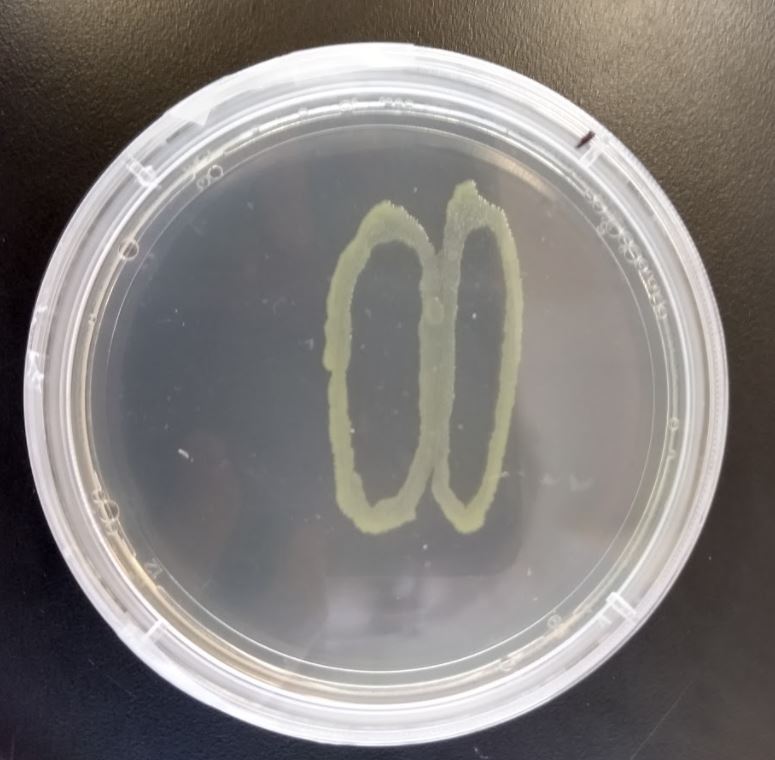
That turns into that:

Staphylococcus is now angry and ready to take a bite out of you (For your meddling experiments.)

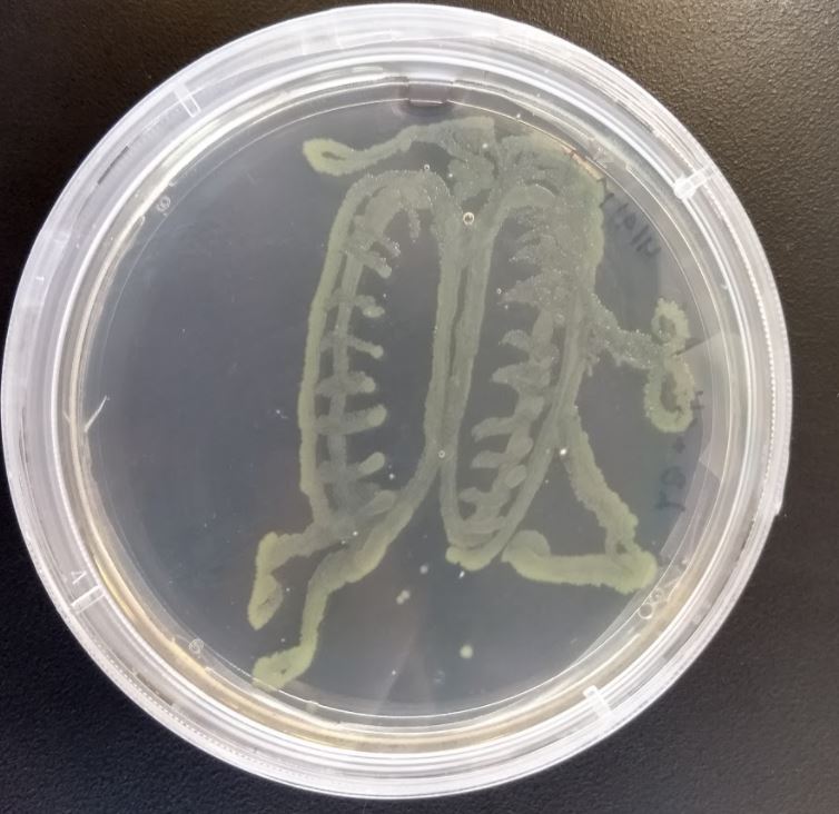
I would like to set up my camera and take shots of growth, but that would require me to be in the lab, taking a picture every 15-30 minutes, for a solid 12 hours. I am thinking that I will make several plates with different stages of the “transformation” taking place, and line them next to each other on the darkreader.

(Concept Picture- I am receiving red glowing bacteria tomorrow from Professor Farny, and would like to use both colors in my art for contrast.)

One of the plates I poured agar into ended up with some bubbles, so I decided to go with it:

Bubble-Eyeball Creature


UPDATE: Day 2 Growth:

Failure and Recalibration

This week I put together the base piece of my project. I was, and arguably still am, having issues with some of the properties of the material I used for it: insulation foam board. Initially, I cut up my pieces and tried to use CA glue (superglue) to put them together. Unfortunately, this was the result:

Turns out that CA glue eats through insulation foam. Not only that, but it actually melts it into a glue-foam slough that gets very messy. After I got it to dry, I tried assembling it with packing tape. I got it stable, but the tape is painfully obvious:

I need tape both inside and out to get everything to stick together, so other than starting over with new materials, I cannot think of a way to do without the shiny effect with the tape. I then tried spraypainting the entire piece, as even in the darkness, the pink is not the color I want to stick with. Spraypaint also melts this stuff. At this point, I think everything melts this foam.

All of that texture effect is because the spraypaint melted the foam. One one hand, adding paint made the tape issue even worse, I need to see if minimal light can alleviate some of that. As for the visible melting, at this point I think I can say it actually turned out for the better, as it creates a more natural-looking asphalt look.

One last minor issue that I’m working through is acquiring materials. Three-way PVC connectors aren’t that common, so the Home Depot trip wasn’t a complete supply run. Thankfully I’ve found most of what I still need online.

Failure, Re-calibration & Iteration

Everett Johnson

This week I failed at one minor thing but was able to move past it. I failed at not getting the correct materials for my project, but ending up making due with what I ordered. I was originally hoping to receive some thicker wire to make the main support structures on my project thicker than just the base material. However what I received was very small wire, so what I ended up doing was using the base wire thickness to create the frame and then double up on it later instead of waiting even longer to create the frame that I desired. I then ended up using the smaller wire I received to act as a thread to sew parts of the wire together. I am currently continuing to build my dragon and will have its frame work probably done by the end of the week where I will then focus on the LED’s and getting them all set up within the dragon, making sure that the light part of this project works as intended and is positioned to not just be super bright but also be visually appealing. Below is an image of the work that I have done on the dragon so far:

Recalibration

I am still very much interested in the laser oscilloscope I showed in class last week, however, I’m still figuring the best way to showcase the shapes the laser makes from frequencies.

Over the weekend, I spent some time experimenting with user control of the sound. The simple solution was to send OSC (open sound control) data from my phone to Max MSP. Each axis of the phone’s accelerometer could control a voice of a pitch, which would allow for a chord to be expressed.

The first test just scaled the data to a band of frequencies from 200hz to 1500hz, an area that the laser seemed to respond to well. It combined all three axis to a single voice.

The second attempt used mapped frequencies for each axis by storing pitch information inside of a [coll] file. This would ensure that pitches did not float absolutely, but instead were snapped to ranges that resemble a piano playing all white keys. A line object allowed floating between these points as they activated, because the “detune” or wave offset of frequencies caused more motion in the laser. It was a bit underwhelming.

Lastly, I ended up scaling all chromatic notes between the axis for more fine tuned control. It still was a bit underwhelming. Other data from the phone, like the light sensor or gyroscope could be interesting, or a combination of the phone data with other controllers like standard MIDI controllers for a “performance” could be more captivating. But ultimately, I don’t think this is compelling.

https://www.youtube.com/watch?v=lRbcbhRGlpo

So for my recalibration, I will focus on composing a piece of music around the shapes the laser produces and filming it. Some questions to ask are, does the music have to sound good? Can it be “non-functional” and thus not harmonious, but just based on the shapes the sound produces? What kind of signal processing effects could be used? Could I combine a precomposed piece that focuses on those frequencies, but “perform” it as a DJ of sorts using the phone accelerometer to manipulate effects and other parameters?

What recording of the sound and visuals will be best to archive this project? Is there a better medium to project the laser on still? Can I combine the recorded video and sound from the laser and further process it with jitter, or is that cheating?

Looking forward to experimenting more.

Maquette

I was thinking of creating a painting of sorts on a canvas and then backlighting it. But then I thought it would be neat to create a cube-like object and have lights in the middle. I started playing around with tissue paper and was hoping to do tissue paper painting, to try using a new medium. Using a small canvas, I created a sunset collage. I was hoping that the colors from the tissue paper would bleed on the canvas, but I accidentally bought the wrong type of tissue paper. So for the sake of the maquette, I glued the papers down.  I cut a cactus out of construction paper and attached it to the backside of the canvas. I thought it would be neat to have an image on one side, and when the canvas is lit up, another image appears.

Going forward, I need to buy:

Bleeding tissue paper

Larger canvases

Paintbrush for water/glue

Exacto knife

Lights for the interior

I am planning to make a small version of the cube once I can get some more of these materials, and also am considering other ways to make an additional image appear when lighting up the cube. Also I need to figure out what the best type of lighting will be, whether I should use string lights or a light bulb style lighting. These things I can test once I have the cube built.

Water Vortex Maquette

For this maquette I wanted to test the size of the vortex as well as how the flame reacted to the swirling water. In order to achieve this I started by first ordering a pump and corresponding tubing. Once these arrived I worked with a few different water vessels in various sizes that I had around the house and decided that between a 4-6 inch diameter vessel will be the correct size with the current pump that I have. By drilling a 2 inch hole into the bottom of the container i was able to create a vortex that was wide enough to keep the flame going.

For the flame I created a miniature alcohol lamp from a small sample jar filled with 91% isopropyl alcohol with Q-tips acting as a wick. This worked well and created a flame that was around 2 inches high without any airflow changes

From these tests I discovered 2  main things. First off, the pump that I have many not be strong enough for any larger scale. As is the water height only reaches about 4 inches high. A smaller vessel or an additional pump may help this. The other observation was that the fire was trying to swirl but did not have enough airflow to make it work. I am hoping that increasing the height of the vortex will swirl more air and achieve the desired affect. Barring this, I may have to create a mechanical solution that physically spins the fire itself to achieve this affect.

Overall I was pleased with the maquette and I really liked how the fire reflected off of the swirling water.

Moving forward I plan to follow this timeline for the next week:

  1. Friday order glass and glass cutter for show vessel and water holding vessel
  2. Saturday figure out if it is feasible to cut glass using wine bottles
  3. Sunday experiment further with different sized vessels too see if I can get the fire to swirl more effectively
  4. Monday – determine how to mount the fire so it will not get wet but still achieves a tall flame
  5. Tuesday – hopefully receive glass and work on cutting actual products.

I also need to source the following materials:

  • Potentially an additional pump:
  • Glass/Acrylic/wrappable Viny cylinder to hold vortex
  • Glass vase for housing water reservoir
  • glass cutting tools
  • Nice looking screen to hide pump
  • potentially a motor to spin fire
  • funnel for easier refueling and possibly protecting the fire from the splash

  • Standard operation of the vortex

Vortex while spraying fire into the chamber

Maquette

For my Maquette, I held the pieces together to try to get them to project on to the ceiling. Unfortunately, this did not go as planned as the pieces did not pick up light as well as I had hoped. However, smashing them was very fun.

I did some other tests with the gems to figure out ways to get this project to work as shown in the pictures below. I put the pieces into a clear plastic bowl and shined light into it.

*Need to fix the pictures to be postable. Will edit to add*

I also tried an infinity mirror with light projecting through a gem and got a cool result as seen below.

My plan is continue experimenting with my first idea by trying different parts and seeing the results. If I figure out that the idea won’t work no matter the changes, my plan is to move to my second idea.

For parts, I do not know everything that I will need at this time. However, there are a few pieces I plan on getting to use and experiment with.

  • Petri dish to put pieces into (My roommate got them for me)
  • Glass pieces
  • Something to rotate the petri dish

Overall, my idea is very much trial and error as seen with this maquette. While my plan is to continue experimenting, I do have a plan for points I would like to reach over the next weeks.

  • Have something that changes colors when moved (4/12)
  • Have a set-up that allows for part to easily move (4/19)
  • Have set-up together in a portable system (4/26)

Maquette~ Lauren Getz

Starting out my maquette I found myself with a literal blank canvas.

After visiting my local craft store I found small canvas squares in a 5 pack for only $4 which I quickly snagged up, spent an additional hour and half going up and down every other aisle, and left.

My initial canvases ready to be painted into “happy” Bob Ross-esque landscapes.

I painted the canvases to look like stars on a night sky in order to have an idea of where to put the LED’s.

I added some grass to the bottom for the idea that it’s a field/ forest sort of landscape.

I realized I don’t know how to count and painted one dark green to act as the base of the open face cube.

I started drilling holes in the canvas, which turned out to make pretty ugly holes instead of the clean effect I was hoping for.

Once the holes were in place I started stringing twinkle lights I had from previous room decoration of yesteryear. It was a pretty long strand so it ended up being a huge hassle to string them through, I ended up just sort of bundling them up randomly in a way that was moderately appealing.

Final setup of my maquette, I painted some trees and other mountain-type blobs in the background for depth. I took the leftover string lights and put them in a bundle in the middle  to represent the light bulb that I couldn’t fit inside the box of canvas well. I made the centerpiece look sort of like a city building with windows, or at least that was my intent.

Doing this maquette gave me the idea to make it slightly more technical by  introducing the idea of LED’s hooked up to a light sensor, so when the light in the middle is on they will automatically be off. The light in the middle will still be manually controlled by a dimmer to make the project interactive with the viewer.

The supplies I believe I will require are:

  1. 5  canvases
  2.  Paint
  3. Glue gun
  4. Arduino Pro Mini
  5. Light Sensor
  6. Light bulb
  7. LED strand

I am planning to order all supplies this weekend to give myself time for assembly. Supplies should arrive by next week some time.

Maquette – Duong Nguyen

For last week:

  • I have created a cardboard version of my design for the cube.
  • I have cut acrylic sheet into part so I can test the one way mirror window film to make the infinity mirror illusion.

  • Tested with the gyrometer

Last week I already started to order parts I need for the project, this is what I have bought so far:

  • Acrylic Sheet
  • Plastic Acrylic scorer (because I don’t want to use laser cutter because it might burn the acrylic sheet and I don’t have a specific dimension for my design yet)
  • One way mirror window film
  • Gyrometer
  • 100 LED RGB strip

What I might need for next week:

Schedule:

Week of 4/8/2018:

  • Finalize design of structure, at least have them fixed so next week I can start to attach the mirror to the holding structure.
  • Start to make the mirror (at least 3)
  • Figure out a way to insert light strip easily
  • Experiment with other way of displaying light, not LED alone but LED with others material

Week of 4/15/2018:

  • Finish making the mirror
  • Fixed and solve any issue for last week.
  • Adding light to the mirror and implement lighting control based on gyrometer

Week of 4/22/2018:

  • Finalize the projects.
  • Implemented any other light function like react to music, if have time.

Maquette, Shopping List, and Milestones

Since last week, I have worked on changing up my project proposal to a static scene of a rainy night.

I built my maquette using cardboard as the platform the sculpture, with one side not closed up to ensure I have a hollow base in which I can hide my wires and power source(s). The bendy-straw frame is there as a placeholder for what the actual scaffolding I use will be: either creating a frame around the base and draping the lights down from the top, or inserting rods into the base to run strings of lights along them. I will create a puddle effect by carving out a section of the base and placing a diffusing material on top to smooth out the light.


Materials I need:

-Strings of warm-white LED lights (likely Sylvania Microdots)

-an umbrella (Amazon)

-MDF or Foamboard for the base (Amazon or craft stores)

-many batteries

-PVC pipe for the frame, or Metal rods to attach lights to (Home Depot)

-Zip ties

-Some material to diffuse light

Milestones:

4/12 – Shopping and base completed

4/19 – Frame/scaffolding built, put together

4/26 – Lights added, Project finished