Overview:
Psycho (the name of the my project) was a super fun project to work on. Psycho is an Audio Visualizer. There is a teensy 3.2 in the back of the neck along with a microphone, the teensy preforms the FFT with the help of teensy’s audio library. the different frequency bins are then grouped according to base, mid, and treble, and those bins are then sent over to the lights, with the dB of each bin corresponding to the brightness, and the hue determined by a random value with in the range of the bin. This may seem a bit confusing but the way if works is that when the FFT is preformed, we then get 512 bins all with 40Hz of band per bin. This covers the full audio range of human hearing 20Hz to 20KHz. for this project only the frequency from 40Hz to 3.6 kHz are used, and the bands are defined as follows 1-6, 6-12, 13-20, 21-30, 31-40, 40-90, in terms of the “bins”. I then iterate though the bins in each band, and look for the bin with the highest amplitude, and the that amplitude gets mapped to the brightness, and the bin number gets mapped to the hue, with a small degree of randomness just to get a little more variance in the color.
example videos of the head working 🙂
BOM:
Lithium ion battery: 18650 2600 mAH or equivalent
Natural PLA 3d printer filament (or any other clear filament that is easy to print)
Bypass capacitor (330 microF)
On/Off switch
hot glue
3D printing:
here is a rendered photo of the head:
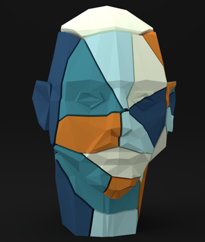
the STL file(s) for the head are hosted here
all the parts were sliced in Cura with no infill, and no bottom layers
the parts need to be positioned so that there are minimum overhands
All of the electronics went into part #6, (in the folder linked above )
Wiring:

the wiring is that, the battery was connected to the batter ports of the charge controller
the + output of the charge controller had the switch connected to it, and the other end of the switch was connected to the + of the capacitor
the – output of the charge controller was connected to the – terminal of the capacitor.
the + of the capacitor was connected to the Vin of the Teensy, and the input of the Neo-Pixel
the 3.3v pin (on the teensy) was connected to Vdd of the microphone
the – terminal of the capacitor was connected to the ground of the teensy, the ground of the microphone, and the ground of the Neo-Pixel
the data line of the Neo pixel was connected to pin 5 on the teensy
the output of the mic was connected to A0 (pin 14) on the teensy
3 lights were put into this back piece, and an Ethernet cord was cut to connect the wire the lights together in-between the pieces
Assembly:
a hot glue gun was used to melt holes between the parts to wire though, about a foot of wire was used between pieces to give so extra room for soldering. the parts were then hot glued together. this part took the longest, around 30 hours to assemble.


Programing:
I started with the teensy Audio library to perform the FFT, as well as the Adafruit_NeoPixel library to control the lights.
I used a separate function to convert the RGB input of the Neo-pixels to HSV so that it was more intuitive to set the color and brightness.
the code is as follows:
#include <Adafruit_NeoPixel.h>
#include <Audio.h>
//#include <Wire.h>
//#include <SerialFlash.h>
#ifdef __AVR__
// #include <avr/power.h>
#endif

void setLedColorHSV(byte h, byte s, byte v);

// Create the Audio components. These should be created in the
// order data flows, inputs/sources -> processing -> outputs
//
AudioInputAnalog adc1(A0); // ADC0 input
AudioAnalyzeFFT1024 myFFT;

// Connect either the live input or synthesized sine wave
AudioConnection patchCord1(adc1, 0, myFFT, 0);

// Which pin on the Arduino is connected to the NeoPixels?
// On a Trinket or Gemma we suggest changing this to 1
#define PIN 5
const int POWER_LED_PIN = 13; // Output pin for power LED (pin 13 to use Teensy 3.0's onboard LED).
byte h;
byte s;
byte v;
byte RedLight;
byte GreenLight;
byte BlueLight;
int currentlight;

float avg_fft[512];
int avg_fft_cout = 1;

#define NUMPIXELS 41
#define NUMCELLS 25
int cells[NUMCELLS] = {3, 2, 2, 2, 1, 1, 1, 1, 1, 1, 1, 1, 1, 1, 1, 2, 1, 2, 2, 1, 1, 3, 4, 3, 2};

// ----------- ALL THE DIFFERENT MAPPINGS THAT I HAVE MADE!!! ---------------------------------------
// even maping base at the neck
int mapping[NUMCELLS] = {0, 0, 1, 1, 1, 1, 2, 2, 2, 2, 3, 3, 3, 3, 3, 4, 4, 4, 5, 5, 5, 5, 0, 0, 0};
// random mapping
//int mapping[NUMCELLS] = {0, 1, 2, 3, 4, 5, 0, 1, 2, 3, 4, 5, 0, 1, 2, 3, 4, 5, 0, 1, 2, 3, 4, 5, 0};
// random mapping base at the left ear
//int mapping[NUMCELLS] = {0, 1, 2, 3, 4, 5, 0, 1, 2, 3, 4, 5, 0, 1, 2, 3, 4, 5, 0, 1, 2, 3, 5, 5, 5};
// random mapping base in the neck
//int mapping[NUMCELLS] = {0, 1, 2, 3, 4, 5, 0, 1, 2, 3, 4, 5, 0, 1, 2, 3, 4, 0, 5, 5, 5, 5, 1, 2, 3};

// --------------------------------------------------


#define freq_bands 6

// defines the frequency ranges for each band
int freq_high[freq_bands] = {90, 40, 30, 20, 12, 6};
int freq_low[freq_bands] = {40, 31, 21, 13, 6, 1};

// stores the results of going through each band
int freq_max_bin[freq_bands] = {};
float freq_max_amp[freq_bands] = {};
float prev_freq_max_amp[freq_bands] = {};
byte freq_hue[freq_bands] = {};
byte prev_freq_hue[freq_bands] = {};


// When we setup the NeoPixel library, we tell it how many pixels, and which pin to use to send signals.
// Note that for older NeoPixel strips you might need to change the third parameter--see the strandtest
// example for more information on possible values.
Adafruit_NeoPixel pixels = Adafruit_NeoPixel(NUMPIXELS, PIN, NEO_GRB + NEO_KHZ800);

void setup() {
// Turn on the power indicator LED.
pinMode(POWER_LED_PIN, OUTPUT);
digitalWrite(POWER_LED_PIN, HIGH);
randomSeed(10);

pixels.begin(); // This initializes the NeoPixel library.
// Audio connections require memory to work. For more
// detailed information, see the MemoryAndCpuUsage example
AudioMemory(12);

// Configure the window algorithm to use
myFFT.windowFunction(AudioWindowHanning1024);
//myFFT.windowFunction(NULL);
}

void loop() {
float n;
int i;
int fft_count = 0;

delay(10);

// ________________________________________________________
// copy initial sample
if (myFFT.available()) {
for (i = 0; i < 512; i++) {
avg_fft[i] = myFFT.read(i);
}
// averge other samples
while (fft_count < avg_fft_cout) {
if (myFFT.available()) {
for (i = 0; i < 512; i++) {
avg_fft[i] = (avg_fft[i] + myFFT.read(i))/2.0;
}
fft_count++;
}
}
}
// ________________________________________________________

int f; // used as intex for band we are in
int bin = 0; // hold on to the current bin

for (f = 0; f < freq_bands; f++) {

freq_max_amp[f] = 0;
bin = 0;

for (i=freq_high[f]; i > freq_low[f]; i--) {
n = avg_fft[i];
if ( n > 0.01) {
freq_max_amp[f] = max(freq_max_amp[f], n);
// recently added might make things worse? we will see...
//if (freq_max_amp[f] == n) {
bin = i;
//}
}
}

if (bin != 0 && bin != freq_max_bin[f]){
freq_max_bin[f] = bin;
// TODO: the bins are off!! bin 5 should be RED!! currently bin 0 is red
freq_hue[f] = 252 - ((f+1%6)*42 + random((freq_max_bin[f]-freq_low[f])*(42/(freq_high[f]-freq_low[f]))));

}

if (freq_max_amp[f] == 0){
freq_max_bin[f] = 0;
}

// set the hue to the bin hue
if (freq_max_bin[f] != 0){
Serial.println();
Serial.print("BAND ");
Serial.print(f);
Serial.print(" amplitude is ");
Serial.print(freq_max_amp[f], 20);
Serial.print("the bin is ");
Serial.print(freq_max_bin[f]);
}
}

// PUSH ALL THE DATA TO THE LIGHTS!!!
// ________________________________________________________
currentlight = 0;
for(int i=0;i<NUMCELLS;i++) {

h = freq_hue[mapping[i]];
if (h != 0 && prev_freq_hue[mapping[i]] != 0) {
h = (h - prev_freq_hue[mapping[i]])/3 + prev_freq_hue[mapping[i]];
}
prev_freq_hue[mapping[i]] = h;

s = 255;
if (freq_max_amp[mapping[i]] != 0.0){
// v = (int)(freq_max_amp[mapping[i]]*1000.0);
v = (int)(freq_max_amp[mapping[i]]*1000.0);
v = (int) abs(v - prev_freq_max_amp[mapping[i]])/2 + prev_freq_max_amp[mapping[i]];

prev_freq_max_amp[mapping[i]] = v/1.1-1;
} else {
//v = ((int)(prev_freq_max_amp[mapping[i]]*1000.0))/2-1;
v = prev_freq_max_amp[mapping[i]];
prev_freq_max_amp[mapping[i]] = (int) prev_freq_max_amp[mapping[i]]/1.1-1;
}
setLedColorHSV(h,s,v);
for (int j=0;j<cells[i];j++) {
// pixels.Color takes RGB values, from 0,0,0 up to 255,255,255
pixels.setPixelColor(currentlight, pixels.Color(RedLight, GreenLight, BlueLight));
currentlight = currentlight + 1;
}
}
for (int f=0; f < freq_bands; f++){
if (freq_max_bin[f] != 0){
Serial.println();
Serial.print("THIS IS THE LIGHT DATA!!, band is ");
Serial.print(f);
Serial.print(" hue is ");
Serial.print(freq_max_amp[f], 20);
Serial.print("the bin is ");
Serial.print(freq_max_bin[f]);
}
}

pixels.show(); // This sends the updated pixel color to the hardware.
// ________________________________________________________


}

void setLedColorHSV(byte h, byte s, byte v) {
// this is the algorithm to convert from RGB to HSV
h = (h * 192) / 256; // 0..191
unsigned int i = h / 32; // We want a value of 0 thru 5
unsigned int f = (h % 32) * 8; // 'fractional' part of 'i' 0..248 in jumps

unsigned int sInv = 255 - s; // 0 -> 0xff, 0xff -> 0
unsigned int fInv = 255 - f; // 0 -> 0xff, 0xff -> 0
byte pv = v * sInv / 256; // pv will be in range 0 - 255
byte qv = v * (256 - s * f / 256) / 256;
byte tv = v * (256 - s * fInv / 256) / 256;

switch (i) {
case 0:
RedLight = v;
GreenLight = tv;
BlueLight = pv;
break;
case 1:
RedLight = qv;
GreenLight = v;
BlueLight = pv;
break;
case 2:
RedLight = pv;
GreenLight = v;
BlueLight = tv;
break;
case 3:
RedLight = pv;
GreenLight = qv;
BlueLight = v;
break;
case 4:
RedLight = tv;
GreenLight = pv;
BlueLight = v;
break;
case 5:
RedLight = v;
GreenLight = pv;
BlueLight = qv;
break;
}
}
Design Iterations:
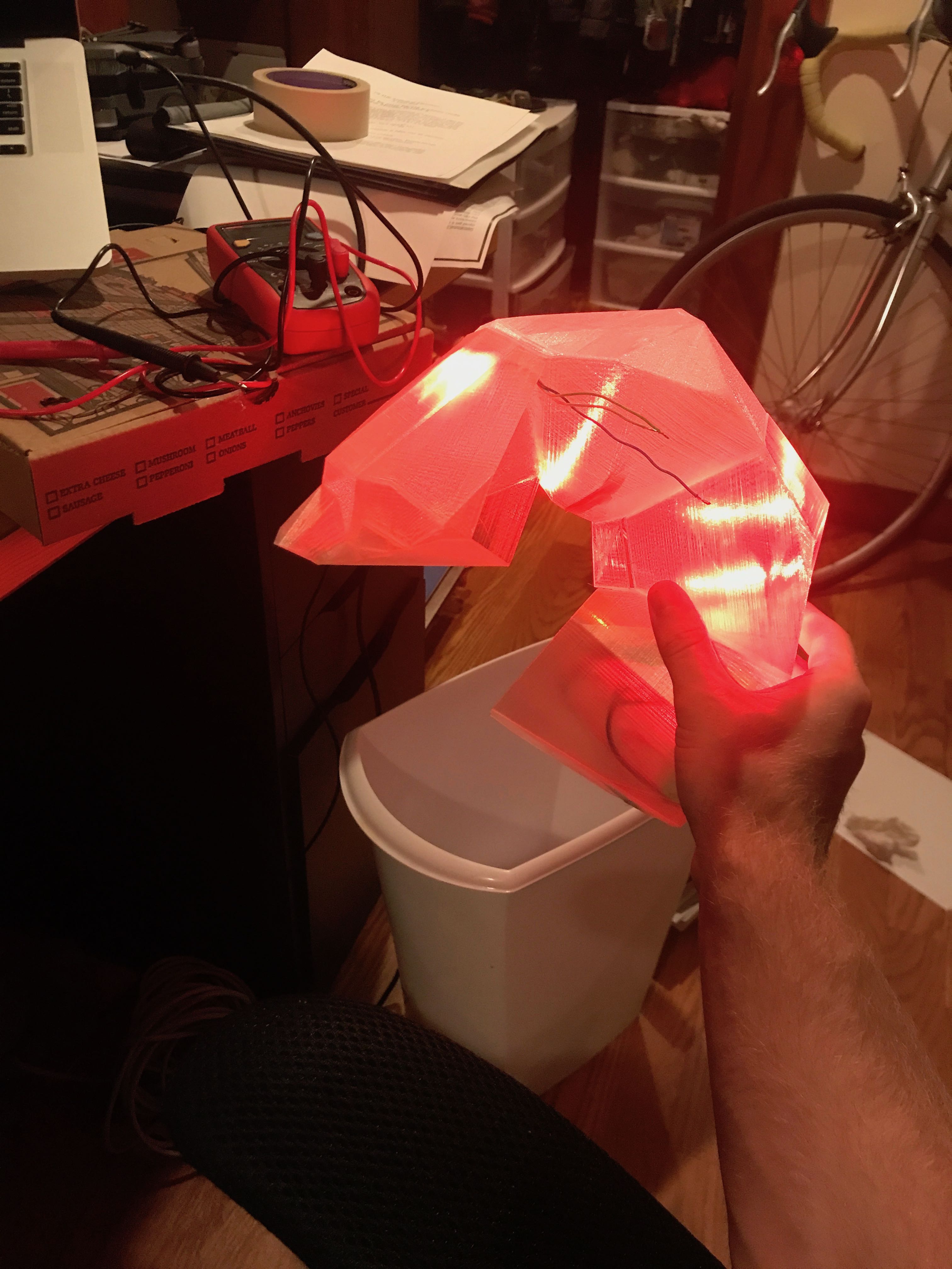
I started with an initial test to see how the 3D printed parts would work to defuse the light
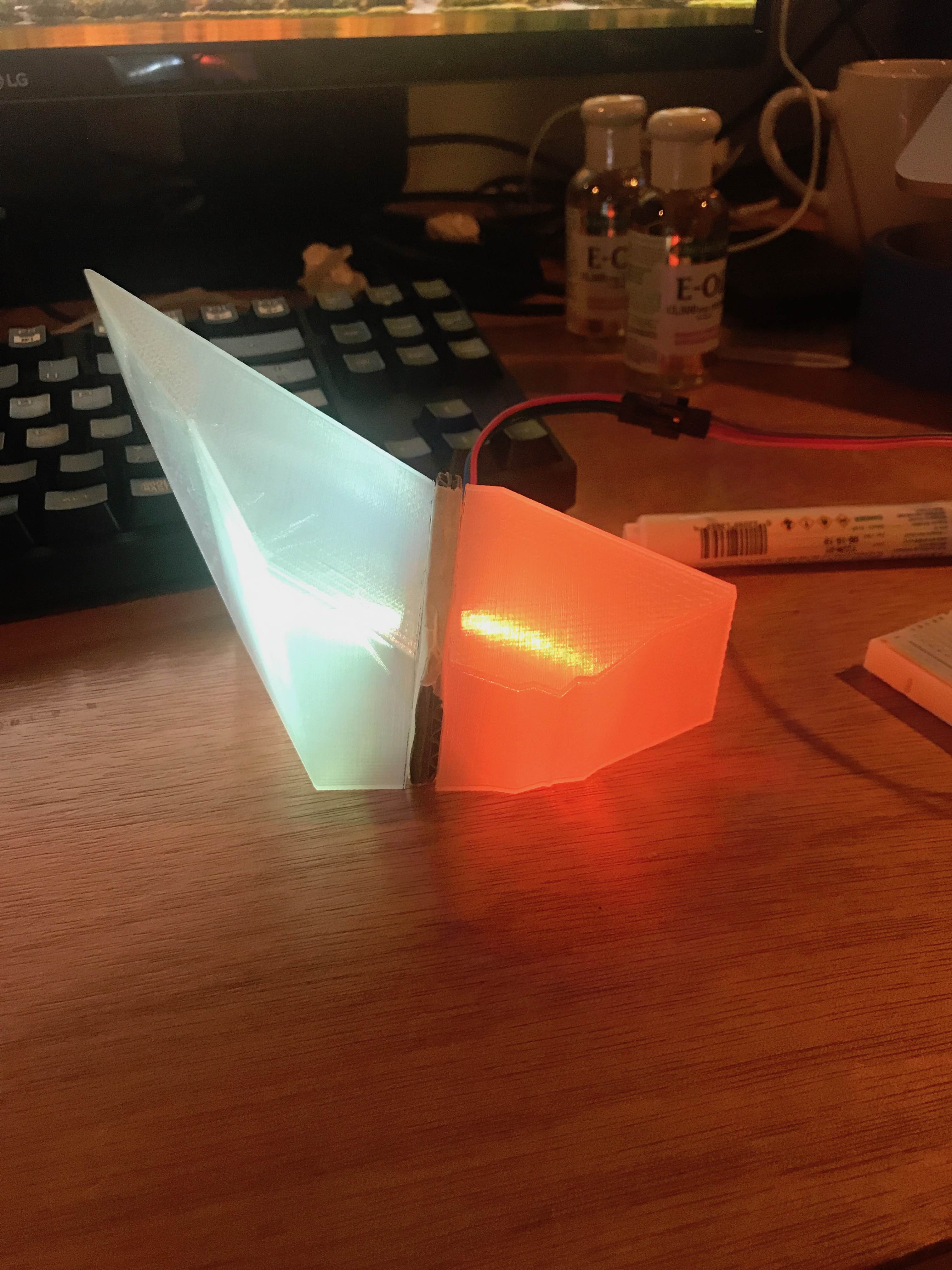
this was a success, for this test I used 2 neo-pixles, and and the Bottom front two pieces of the neck.
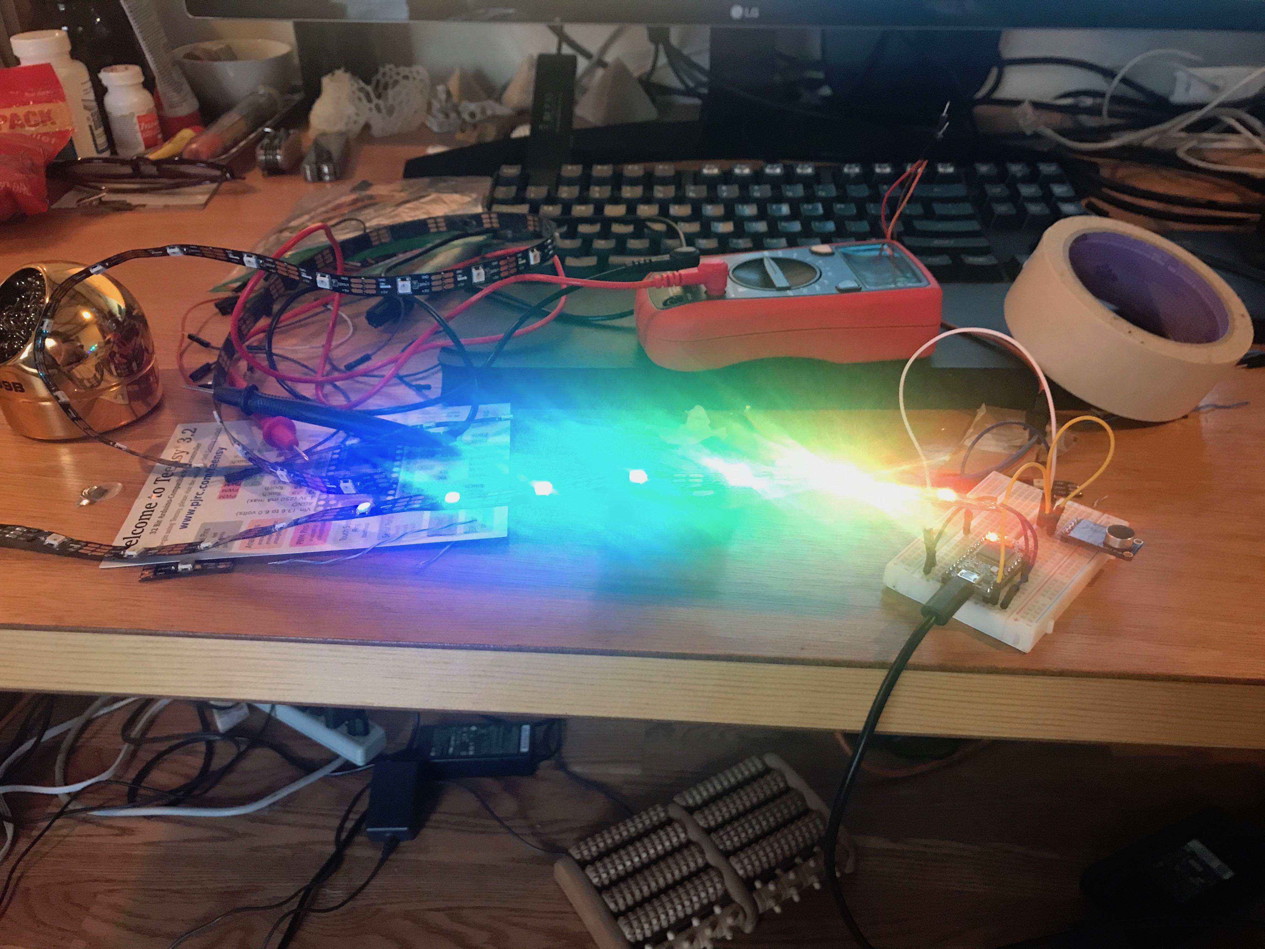
Next I tested out preforming the FFT:
for this iteration I did not use the teensy Audio library, and so the FFT was not as good, the lower frequencies were too sensitive. And I believe the mic was always picking up the DC offset of the microphone, for this part I only have a picture showing the different frequency bins, as a test.
with these two tests complete, and some nice results I felt like I was ready to start assembling the head after all the pieces were printed
images of the assembly are above ^
after everything was put together it was time to get the teensy to work:
there were a lot of iterations in the Code
1 first I just had a script going through and randomly assigning colors to all the lights in the head
then I started playing with the teensy Audio library, which is an amazingly powerful library for audio processing. I found the FFT example, and ran with it.
the documentation was a little limited from what I found online, what was best was going directly into the source files, and from there the code is well documented, and I was able to figure everything out.
In the lab:
I found some contradictory information online, the ADC input for the audio library was stated online to require a DC bias of .6 and a max voltage of 1.2 and a min voltage of 0. So I tested this on the board by brining it in to the ECE lab.
I used the function generator and attached it to the analog input that I was using, I try initially with a 10kHz wave of 1.2 V peak-peak, and ran my script, I then tested with a 3.3 V peak-peak and 1.25v offset, and found that the ADC was able to digitize the whole waveform from 0 to 3.3V which is what I expected from the beginning.
with those tests done, I also tests the microphone in different settings, playing with the gain, and the Attack/Release ratio (not quite sure what it is but it has settings). and found that the default setting gave me the best results.
bands:
now that all that nonsense was out of the way, started dividing up the frequency bins in the code
initially I had 6 bins from 40Hz to 20kHz but quickly found that there was not much being picked up at the higher frequencies.
I had by bands divided according to this guide for sound:
https://www.teachmeaudio.com/mixing/techniques/audio-spectrum/
| Frequency Range | Frequency Values |
|---|---|
| Sub-bass | 20 to 60 Hz |
| Bass | 60 to 250 Hz |
| Low midrange | 250 to 500 Hz |
| Midrange | 500 Hz to 2 kHz |
| Upper midrange | 2 to 4 kHz |
| Presence | 4 to 6 kHz |
| Brilliance | 6 to 20 kHz |
but I was getting very little presence and brilliance so I scaled all by bands down to make it look better.
and ended up going from 40 Hz to about 3.5KHz and got some good results
averaging:
I was trying to average multiple FFT together to try to get rid of some noise, but what I found was that I forgot to check if I was getting the new sample before I was averaging it in, so what this equated to was wasted CPU time that was just sort of a delay, but it looked nice.
So I fixed the code and then I found that by doing this, the lights were flickering a lot, and I tried to apply a moving average to all the samples, but still wasn’t giving the results that I wanted, so eventually I gave up and put back in the delay. this is something that I plan on fixing in the future, because I want the head to me more responsive to the audio coming it and be able to fade appropriately, I think that is the one thing really missing from the project.
light layout:
I played around a bit with the light layout, at first I just mapped all the lights to the different bins in order from 0-5 and repeating till the end of the cells. It gave a pretty nice look, but I like the base, so I decided to make half of the face just dedicated to the base, and then I was happy with the results and think that it looks really cool. So the left half of the face glows red with the base.
Music:
finally what was left was to find the songs that I thought make the head look best, for this I recruited my roommate Steve (he has some nice speakers) and we sat in his room listening to music and watching how the head responds. Great experience would recommend
Future improvements:
better attempt at the moving average
re-ordering the lights
dividing up the frequency bands a bit better
making more heads
adding the entire process to my GitHub.