Josue Contreras and Chris Bell
Presentation Description
We set out to create a light art project that would be an interactive experience for the individuals that entered the room. Our team researched light artists who specialized in creating unique interactive projects and were inspired to emulate an interactive installation of our own to fulfill the Light Art Practicum Humanities Project.
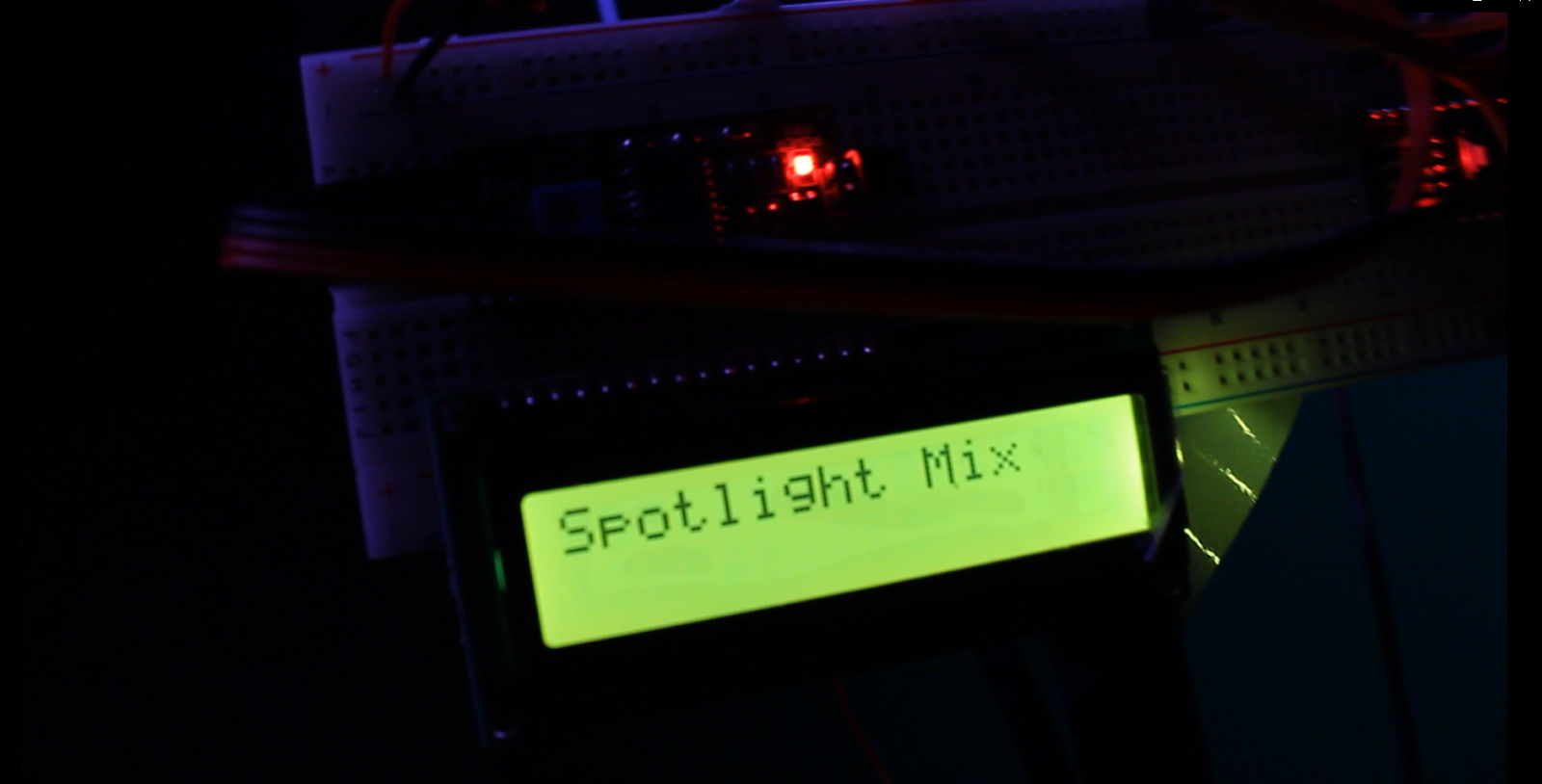
The idea behind Spotlight Mix was to simulate a party where the more users that entered the area of interaction, the more lights would light up around every individual and the more instruments would be added to the overall song. Therefore, if the interactive space was empty, no lights would be lit up and no music would be playing. When the first person enters the space, this would cause the LED lights surrounding the participant to light up (creating a spotlight effect). Additionally, a randomly selected drum beat will play when the first person enters the space. The more people interacting with the piece would cause more lights to turn on that surrounded each individual. For the musical side of things, the second person would trigger the bass of the song and the third and fourth individuals would trigger additional random melodies that add to the overall song. Since the maximum number of individuals who can interact with the installation is four, additional people entering into the area will produce no effect. It is also important to mention that the song generated by the four individuals is always randomly generated. This idea of an interactive art installation coming to life because of the audience was derived from the light artist Rafael Lozano-Hemmer, “If nobody shows up, there’s no show.”
Technical Description
Github Repo for Spotlight Mix: https://github.com/cbell2/LightArt
Computer Vision
Library used: Opencv for Processing
How to obtain this library: Download it from the processing IDE Sketch tab->Import Library->add Library->Search “Opencv for Processing”->click on download
The project incorporates computer vision in order to detect how many users are in the targeted area and their locations. Because of this, a webcam is needed in order to run the project. Our team decided to use the Logitech QuickCam Pro 9000 webcam with a 16.4 ft long usb 3.0 extension cable to be able to mount it on the ceiling and still interface with it. In order for the program to accurately detect the individuals or objects in the space, visually-distinct colors must be used and the lighting on these colors has to be evenly distributed in order for the camera to accurately detect them. Since the perfect color lighting distribution cannot be achieved in such a light changing environment, a range of hue values is created and extracted from the hue in the HSB converted image. Once the pixels with these hue values are segmented, the images is eroded to remove small objects from the image for a smoother border. Finally, using post-processing, the contours of this segmented objects are found and the biggest contour is chosen as the object to track. The intrinsic value of the camera is then extracted as the position of the object in the space.

Image Processing Flow
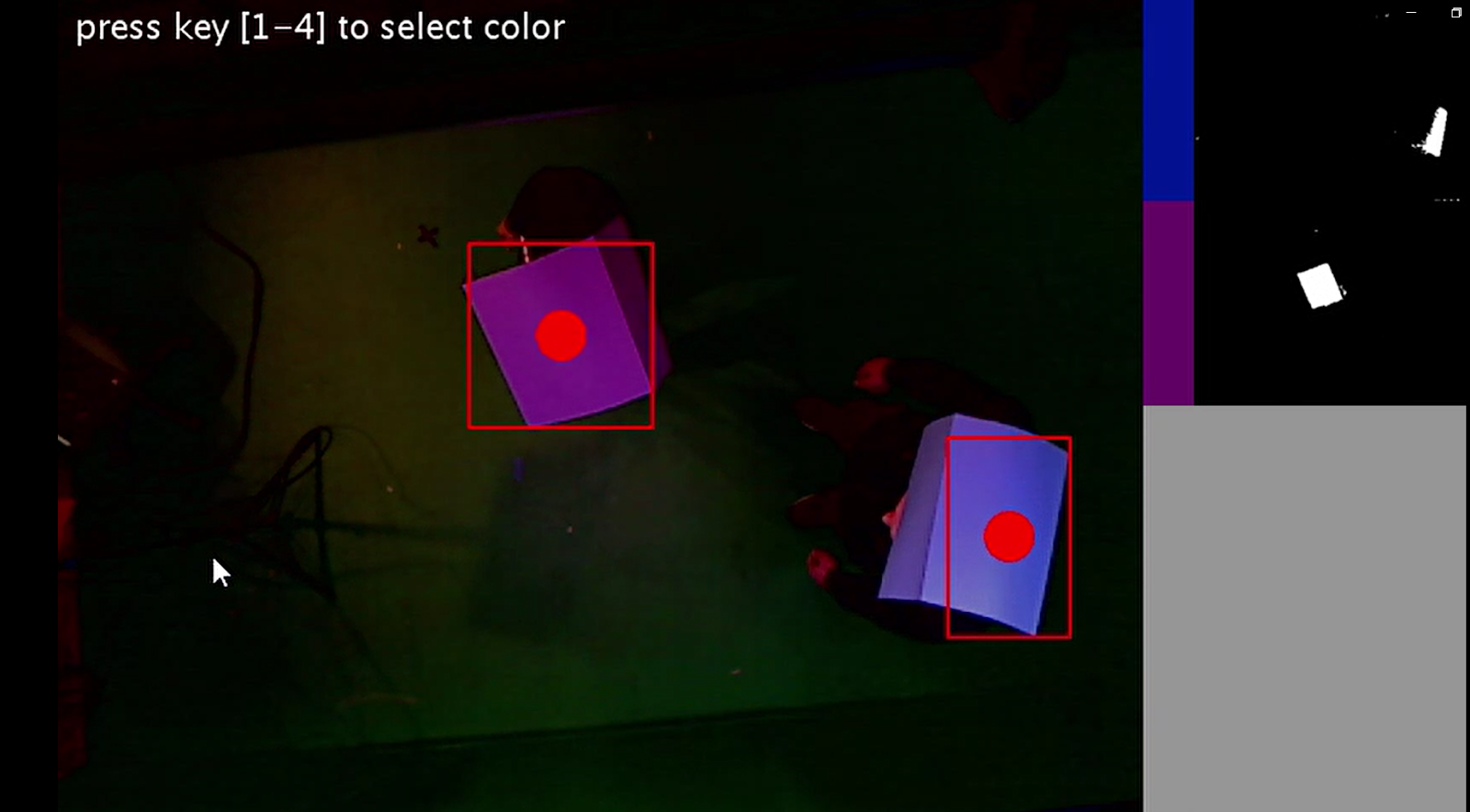
Image segmentation and information extraction
This code was not written by our team, but it can be found as part of the examples that come included with the OpenCV for Processing Library. The example name can be found by opening processing->File->Examples->Contributed Libraries->OpenCV for Processing->”MultipleColorTracking.” This processing program used can detect up to four colors the user can set through clicking on the color within the provided camera view window. This is helpful since, instead of hardcoding a color value that can change depending on the environment light, it can be dynamically changes as the program runs to get the best color detection. The team used this example, but modified it by adjusting the hue detecting and multi-person tracking to fit the needs of the project. The modified color tracking example can be found in the team github repository.
Music Integration
Library used: Minim
To create the music aspect of the project, we downloaded a library of sound files that all coalesce to form one song and randomly generate one per color detected by the computer vision program. The sound files downloaded from the library are categorized into three categories: drums, bass, and melody. The first sound file chosen, which starts playing when the first person enters the installation, is always a drums file. The second is always a bass file and the third and fourth are both melody files. The specific file chosen within each category are randomly chosen each time they are triggered to play. Therefore, if a user entered the installation, exited it, and then re-entered, two different sound files should be played. The original sound files are from Madeon’s Adventure Machine, which can be found here: https://www.madeon.fr/adventuremachine/?.
LED Interactions
Library’s used: FastLED, LiquidCrystal_I2C, and WIre
The 300 addressable LED Strip was split in two and positioned on the roof parallel to each other. The camera was setup in between the set of LED strips and had full view of the space between these as seen the figure below.
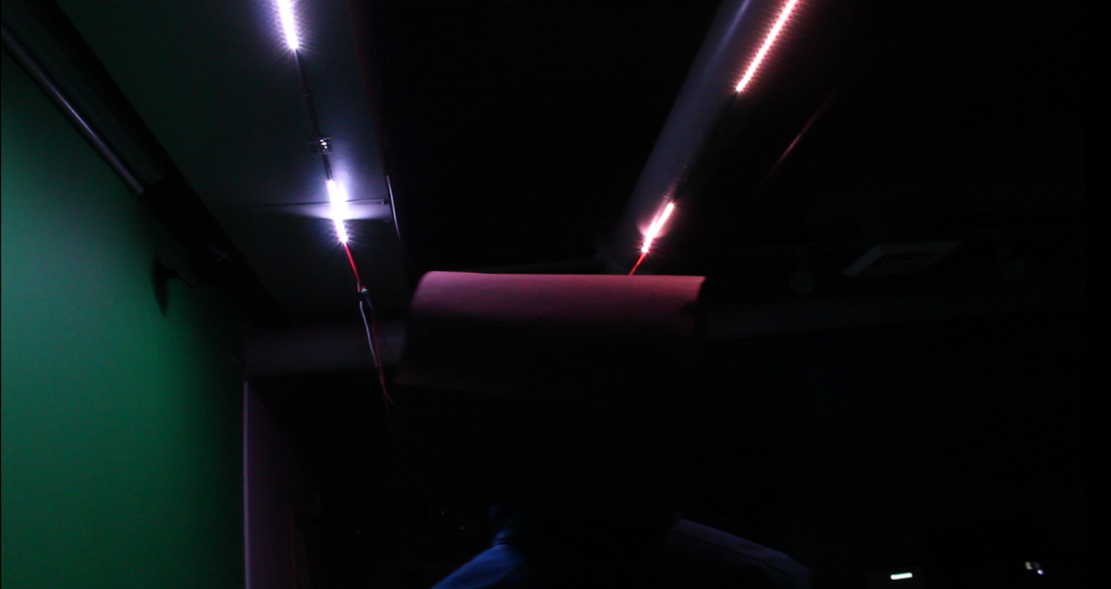
An Arduino Nano was used to interact with the LED strips along with a 5V 3A power supply. For the code our team used the FastLED library and the LiquidCrystal_I2C library for the LCD that was used for debugging and displaying purposes. The main function to light the two arrays of 150 LEDs is called personHalo(). This function takes in two parameters the x position values from the detect objects in the space and sets it as the middle LED. Then a simple algorithm was created to light up a threshold of LEDs surrounding that middle LED to create the spotlight effect around that object. Four colors can be set with the right rgb hex value that can be found in the FastLED documentation: https://github.com/FastLED/FastLED/wiki/Pixel-reference. There is also a function called personBell() that surrounds the object as the previous function, but it fades the LEDs as they are farther from the object. Finally, the x positions acquired from the object detection are received through arduino’s serial port. To parse this packet of four position values for the for objects we used the getValue() function form the following link since it suited our needs: https://arduino.stackexchange.com/questions/1013/how-do-i-split-an-incoming-string. The code described in this section can be found in the github repo for this project under the “LED_strip_interaction” folder.
Program Communication
Communication from the object detection program to the sound and arduino program proved to be the biggest challenge. The computer vision for object detection (color detection) is a time extensive process. This then presents the challenge of how to manage the two other processes (sound and LEDs) so they can be updated in real time and not be delayed by the computer vision processes. To solve this our team called the object tracking, sound, and LED strip programs nodes. These nodes can run separately from each other and, in order to link these nodes, we created messages. These messages are simple text files in the folder. There is a text file for sound and another one for the x poisitions of the objects detected. The object tracking program writes a concatenated message to these files on every iteration of its processes. Then these files are read by the sound and LED strip programs and parsed to be interpreted. Processing has a built in library that allows to read and write to files. But arduino is not capable of reading or writing to files. Communication to arduino is only done through serial. Therefore, a simple python script called packetSender.py was implemented by our team to read the message form the file and write it to serial for arduino to be able to receive it. This communication devised by the team allowed for the programs to be run separately without having to rely solely on one program. It also separated the code into its respective processes which allowed for easier debugging.

How to Run
Materials Needed
- 1x LED Strip (300 individually addressable LEDS)
- 1x Webcam (Logitech quickcam pro 900)
- 1x Arduino Nano
- 1x Computer
- 1x 5v 3 Amp Power Supply
- 4x Colored objects (different colors)
- In this case we used hats with evenly distributed construction paper
- 1x LCD screen (optional)
Directions
Layout
- Find an elevated ceiling for the LED strips and place them parallel to each other with space in-between
- Connect the LED strips to the Arduino and 5V 3A power supply
- Connect the Arduino to the computer running the software (to run software look at the next section)
- Connect the webcam to said computer and place the webcam it in a very elevated position so it can capture the entire area in-between the LED strips
Software
- On windows run “LED_LightArt.bat”
- This will start the computer vision and sound processing files
- In the two processing files the .bat file opened make sure the path for the .txt file matches your current path. Also make sure the port for the camera is selected correctly.
- Start the two processing files the programs the .bat file opened.
- Select up to four colors you want the computer vision to detect in the window showing the webcam view. To select a color press on a number key (1-4) and then click on the color on the screen.
- Open the Arduino file “LED_strip_interaction” and run.
- Finally run the python file “packetSender.py” to start communication between processing and arduino.