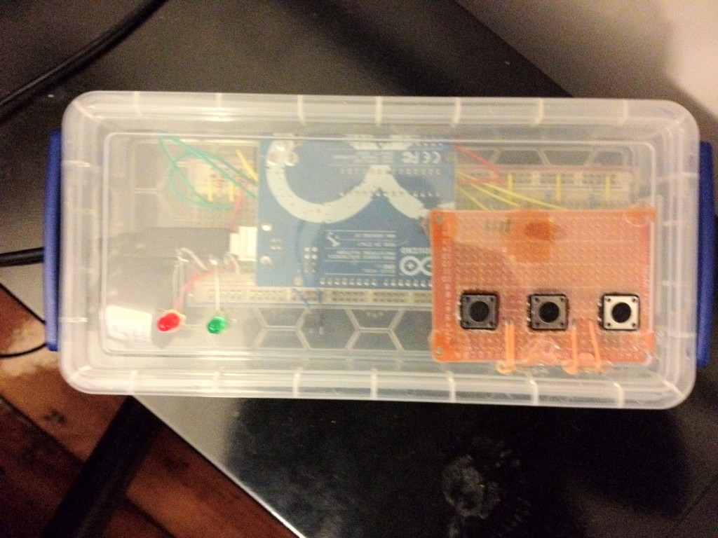
After the code was mostly complete, and the images were filled with temporary place holder art, it was finally time to get the hardware into a permanent state. I found that the box that the Arduino and components came in had a very sturdy base and could be adapted to sufficiently hold the hardware. In order to mount all of the buttons, the tilt sensor, the buzzer and the LED’s, a few hours of ingenuity and effort were required. To mount the button, I borrowed a perforated board from my roommate, and stuck the push buttons onto the board. Using a dremmel, I cut out three square holes on the top of the box and hot glued the perfboard to the underside of the box lid. For the LED’s that indicate whether an action is correct or incorrect, I made 2 small dremmel holes so that the leads of the LED’s went inside of the box and the LED heads stuck on top of the lid. A large hole was then cut out of the side of the box in order to allow the USB cable to connect into the Arduino. Finally, I used the breadboard’s built in adhesive to stick it permanently to the bottom of the box while carefully rewiring and positioning the Arduino inside of the box to limit movement. A picture of the final hardware design can be found below.
IMGD3x00 B term 2012
Inter-Media Electronic Arts

