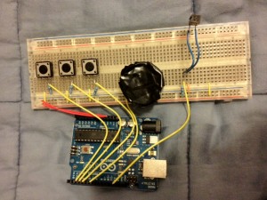
Once my sketch was compiled, and I could get the blinking built in LED on my Arduino board to interface with my processing sketch, it was then time to build actual circuits. The kit I received came with multiple sensors, most notably, a tilt sensor, 5 push buttons and a piezo buzzer. In order to hook up all of the circuits, I found all of the schematics online, which thankfully came with somewhat documented Arduino tutorials to show how to connect each of the devices. The first step I learned how to accomplish was to set up power for the entire board. I ran a red wire form the 5v power supply on the Arduino board to my breadboard, and followed that up with connecting another red wire from GND on the Arduino to GND on the breadboard. Once that was setup, it was finally time to hook up the first push button. Following given tutorials on the Arduino website, I found an example sketch in the processing library that checks the input of all the pins on the Arduino and was able to register a button press on the Arduino from processing! Once the first button was created, the next two followed suit and finally I had all three buttons on my breadboard fully implemented. The next two components, the tilt sensor, and the buzzer were relatively the same circuit setup. The only difference between the implementing the buttons and the tilt sensor/buzzer is simply the code needed to activate and deactivate the triggers. The tilt sensor works by moving a ball inside of a black box, where once the ball makes a connection with the side of the box, it completes the circuit making the pin go high. For the buzzer to be active for a set period off time, the implementing code must have a manual digital write to the accompanying pin to cut the connection and stop the buzzer. A completed circuit with all of the sensors and buttons added can be seen below!
IMGD3x00 B term 2012
Inter-Media Electronic Arts

