I’ll start with final presentation videos, then follow with a final blog post with final steps / updates since the last update.
Finished Documentation
Videos showcasing the project in various lighting conditions, showing both the piece itself and the light effects on its surroundings.
Credit to Zeke Andreassen for assistance with wiring and soldering.
Filming location provided by Charles Baldwin.
Everything else made and designed by me (H La Vallee)
Final Updates
As you have seen, I have made a lot of progress since the last post. As of 4/21, much was still in the planning / CAD stage. Since then I have not only finished designing and printing all 3D printed parts, I have painted and drilled holes in the main sculpture, and assembled everything together.
Wiring / Internals
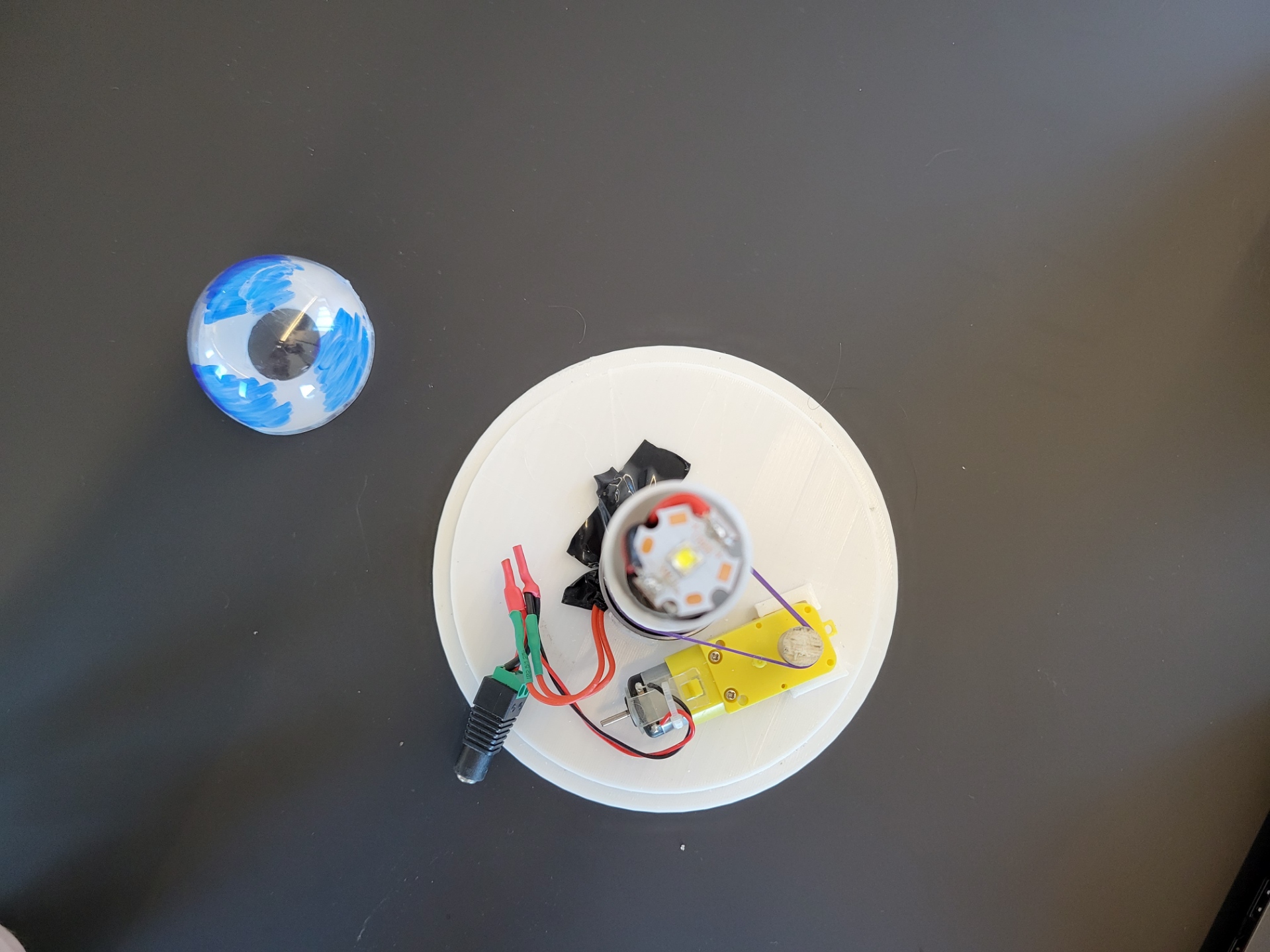
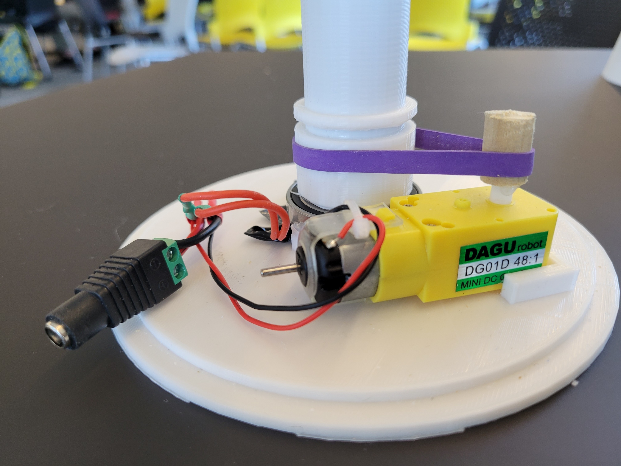
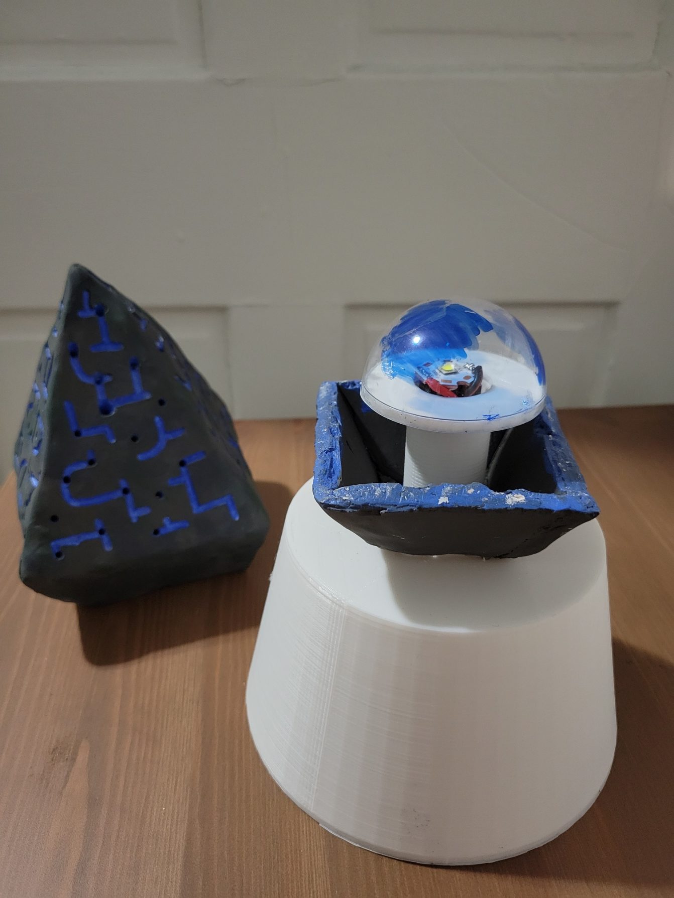
I have printed the tee-piece, shown in the photos above with and without the cap+light shroud on top. After many trials I decided on a simpler approach to the belt design, using a wooden dowel and rubber band instead of the notched motor cap piece. After printing the bottom of the base (which includes mounts for the motor and the bearing), I could attach the wiring and aluminum stick to the base, and snap the motor and bearing into place.
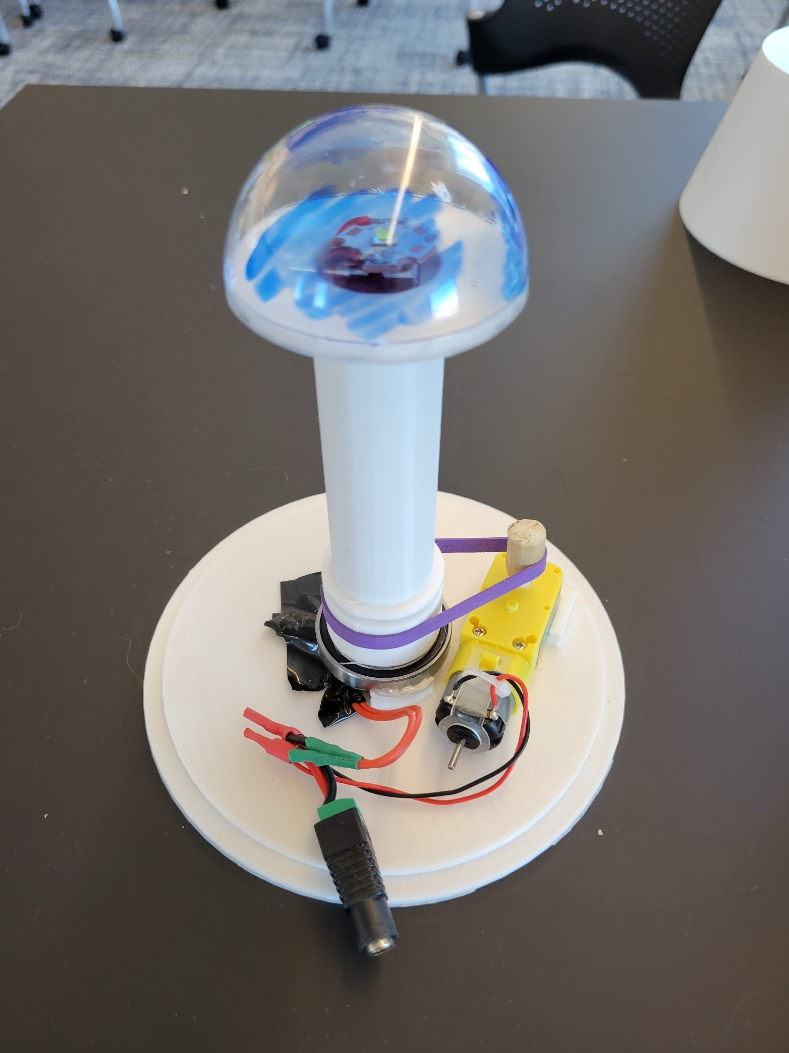
Main Sculpture and Assembly
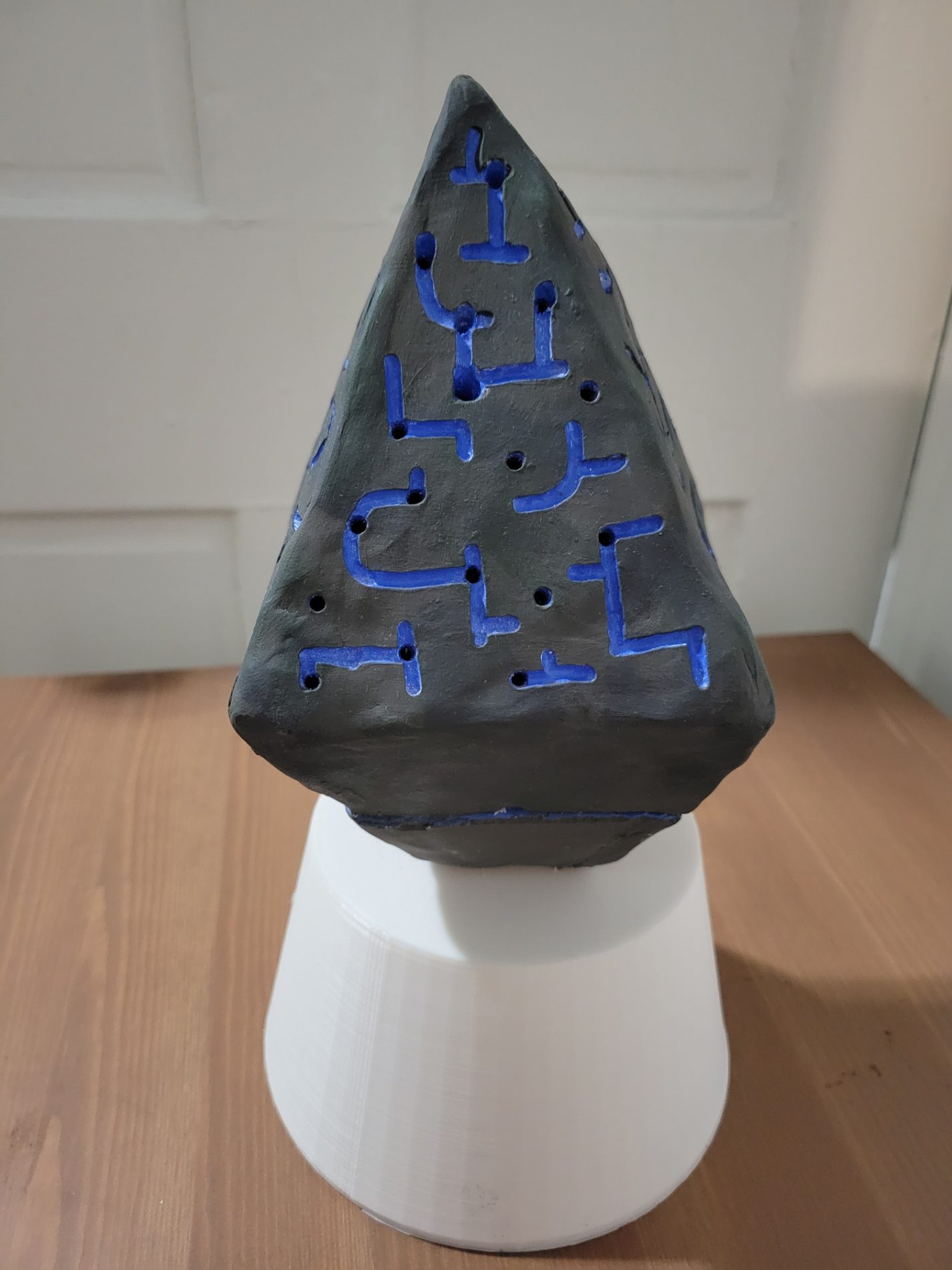

I have drilled holes for the light spots, and painted the main sculpture. Unfortunately, the paint is too opaque to allow light to shine through the thinner parts of the design. I actually drilled holes the wrong way at first, perpendicular to the face instead of pointed towards where the light will be mounted. I had to re-drill many of them, which is why there are larger blue areas around some of the holes (the clay was prone to chipping even with the dremel tool). I also painted the interior of the sculpture with one coat of blue to prevent the pink clay from being seen through the holes. Overall, I am very happy with the design and paint finish!
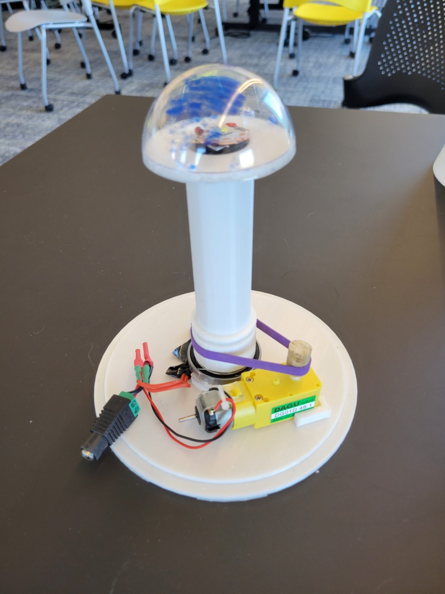
Once completed, I glued the bottom part of the sculpture to the base and made registration marks to be able to easily tell which way to put on the top. The wiring fits neatly within the base, and there is a hole cut in the bottom side to press-fit the barrel jack plug.
I really like the lighting affect on the room, it looks like twinkling stars in the night sky. I could see this being used as a nightlight if you swapped the motor for a quieter one.
Oh my! the beauty of microcontroller-less logic control! I was shocked when I learned that you used a motor to do the colour switching instead of a microcontroller. Way to go!
The clay sculpture and the light effects are looking really neat. But my favorite part about this piece is how elegant the electronics look inside. A very polished piece!
Looks like something straight out of a videogame. Really cool execution!