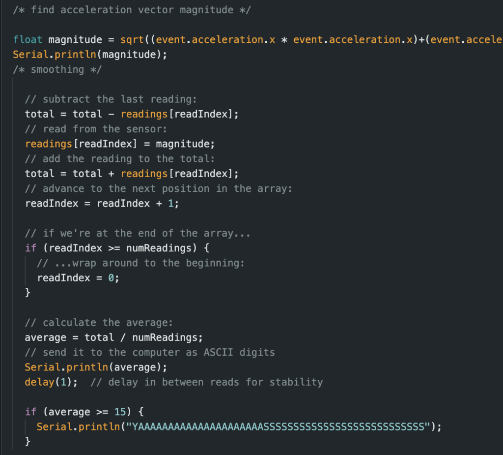
I first decided to tackle writing code to smooth the acceleration data and add a threshold value that triggers the EL wire to be powered. I was able to use a moving average filter to complete this task. It went very quickly so I was able to work on another difficult aspect of my project.

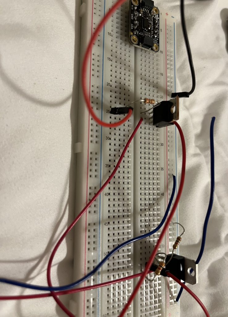
I moved on to powering the EL wire and switching it on with the arduino. My original thought was that the inverter could be powered directly from the arduino, but I measured the current required for the EL wire and it was more that what the arduino can handle. So I looked into how to power the EL wire separately but switch it on and off with the arduino. I built the circuit shown below which connects a 12V DC power source to the inverter by stepping down the voltage to 3V. The voltage converter is also connected to a switch that can be controlled by the arduino. Once I built this circuit, I was testing it with a power source but accidentally powered my EL wire inverter directly with 12V and probably fried it because it did not work after that. I had to order more EL wire, but the circuit should work once I receive the new wire.

Sorry you fried your EL wire, I’ve been there with other components. What are you planning to make the lights do when you receive acceleration data?
I plan on turning them on once they reach a certain speed and off once they dip below that.