For my project, I choose to go with the animated neon sign. I liked how the Neon sign was more personal to me, than the other two projects. However, I do think adding a hidden UV message into the design would be very cool. If time is applicable for my project, I can look more into it. My primary focus is to get the Neon sign fully operational, and then possibly look into ways to improve the design.
For my Maquette, I demonstrated the computer signaling using LED’s to represent the Neon strips. From the video, the microcontroller essentially acts as a timer for when the LED’s are on or off. After some time, the logic value changes depending on the previous state. Below is a video showcasing the LED’s changing.
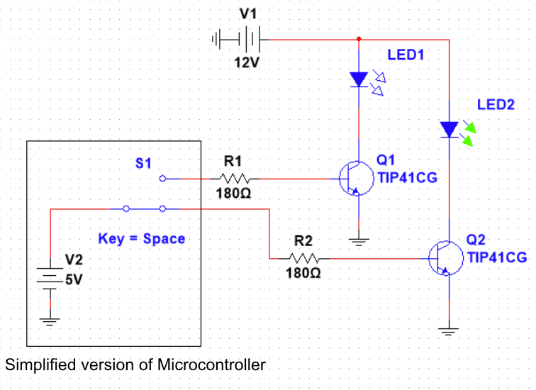
Below is also my shopping list for the project. Note that the reason why I am buying two transistors and two resistors is that the microcontroller cannot supply enough current to power the Neon LED’s (It takes about 3A to fully power a strip (.6-.8A/m)). The transistor acts as a switch that will allow current to flow when there is a positive 5V across the pin of the microcontroller. The resistor is there to limit the voltage, as it only takes .7V to turn the transistor on. Below is a schematic representation of how the circuitry will work for the Neon Sign.
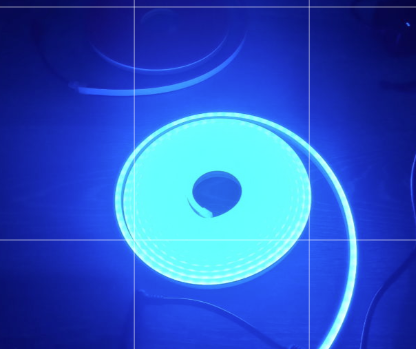
Also in class, I showcased one of the Neon strips that I had purchased. Below is an image of the Neon strip illuminated. Below is also an image of what my schedule will look like for the next two weeks.

| Date: | Task: |
| April 5 | Get the programming of the Maquette done |
| April 6 | Present Maquette |
| April 7 | Begin working on soldering components together |
| April 8 | Draw out locations for each hole |
| April 9 | Drill holes into acryllic (Test if brakes) |
| April 10 | Continue Drilling/screw in clips |
| April 11 | Put in designated wires to areas |
| April 12 | Solder wire connections to each other (in series) |
| April 13 | Hopefully be close to finished- somewhat of a break day |
| April 14 | Finalize solder connections and test |
| April 15 | Hopefully should be done with sign by then |
The neon LED strips are really cool. I liked Josh’s idea of cutting slots in the acrylic and pressing the silicone into the slots. You could even add another layer of acrylic behind the slots so they all sit at the same height, and then you wouldn’t need to worry about not being able to support closed shapes.
That is a potential idea. The only issue I have been running into is getting a large enough sized acrylic, but I appreciate the feedback.
Very detailed list and circuit design! I liked the neon lights so much because how well it works
You could also try using a staple gun to keep it into a softish surface
I didn’t think of that. I could potentially look more into stapling the LED strips down, instead of having to drill holes and screw nails in. Thank you.
Hello, I am impressed with the use of laying out your circuit! The LEDs look really bright and I’m excited to see how it turns out! I was wondering what your plan would be to shape the LED strips, and how you would deal with corners and maintaining shape.
Thank you. My plan was to drill holes into the surface and use clips that came with the strip. The ideal outcome for corners would be to make them flow smoothly, by putting two clips on both ends to maintain shape.