Inspiration
My inspiration from this project is actually from a misleading advertisement I saw online. The ad was showing a “3D Display” for CAD work. This display wasn’t actually 3D, just a normal display that was translucent. False marketing really annoys me so i decided to fix it and make what they were claiming to sell!
Concept
A display that works in 3D. The concept was to achieve the 3D factor by spinning a LED array about a vertical axis so the LEDs take up a volume. By quickly updating the LEDs many times per revolution it allows for persistence of vision (POV) where it appears the light doesn’t move even though it lights up in multiple places at different times. I wanted a display that would pull from a computer the same way a monitor would, but that wasn’t possible in the scope of this project.
When I was presenting my initial project someone found a small example video of something similar to what I was trying to create. It was one color and displayed a cube, but it proved it was possible. After lots of further searching this is the only 3D display that worked in a similar manner.
Initial Execution
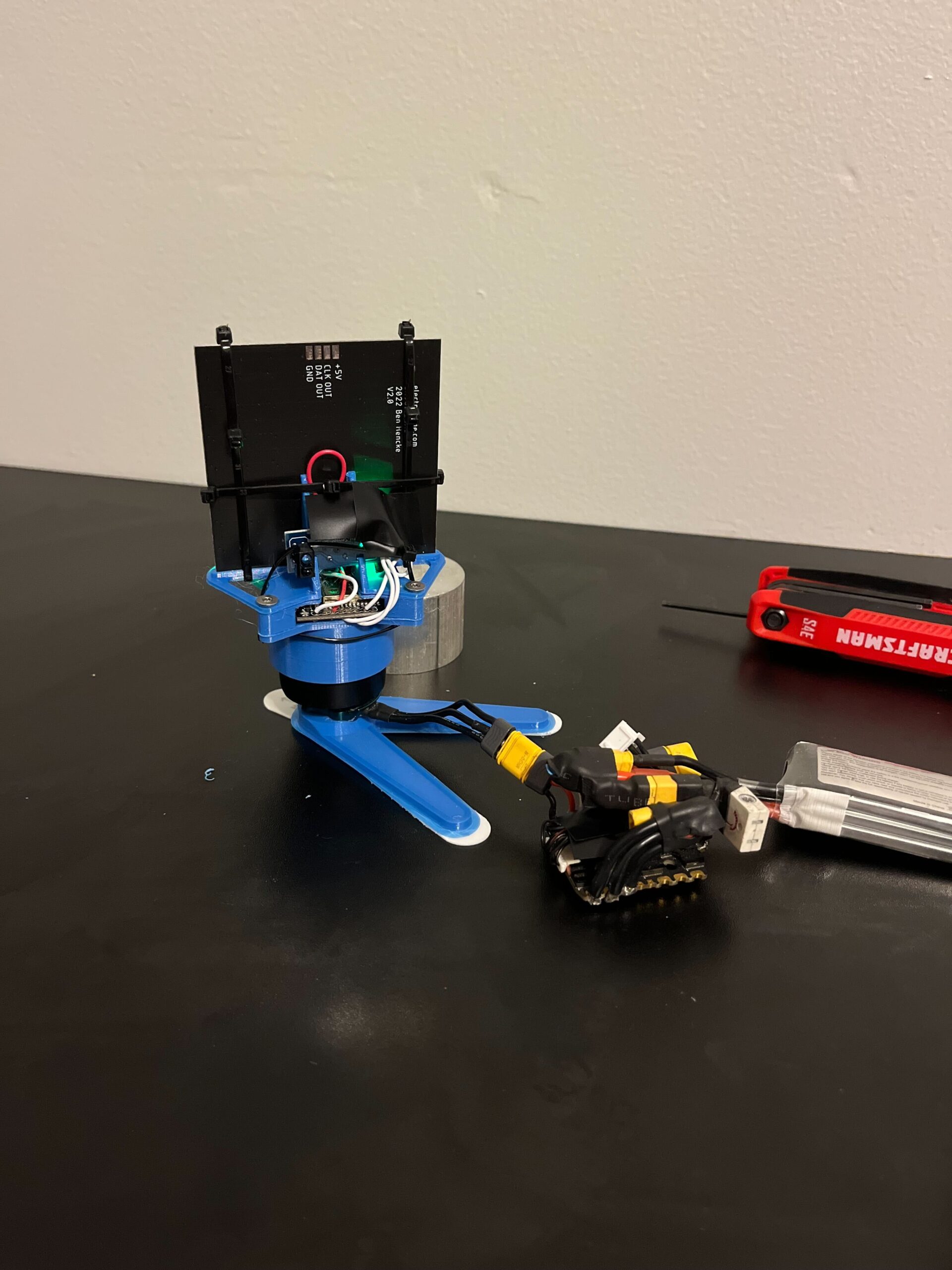
The system to display the 3D image is broken into 2 main parts: the static electronics and the spinning ones. This could be 1 system but moving power between a spinning object and a stationary object is prone to issues.
For the static electronics I planned to use an electronic speed controller that I already had along with a small brushless motor to spin the system. This would be controlled by an ESP32 and powered with a LiPo battery I already had from my combat robot.
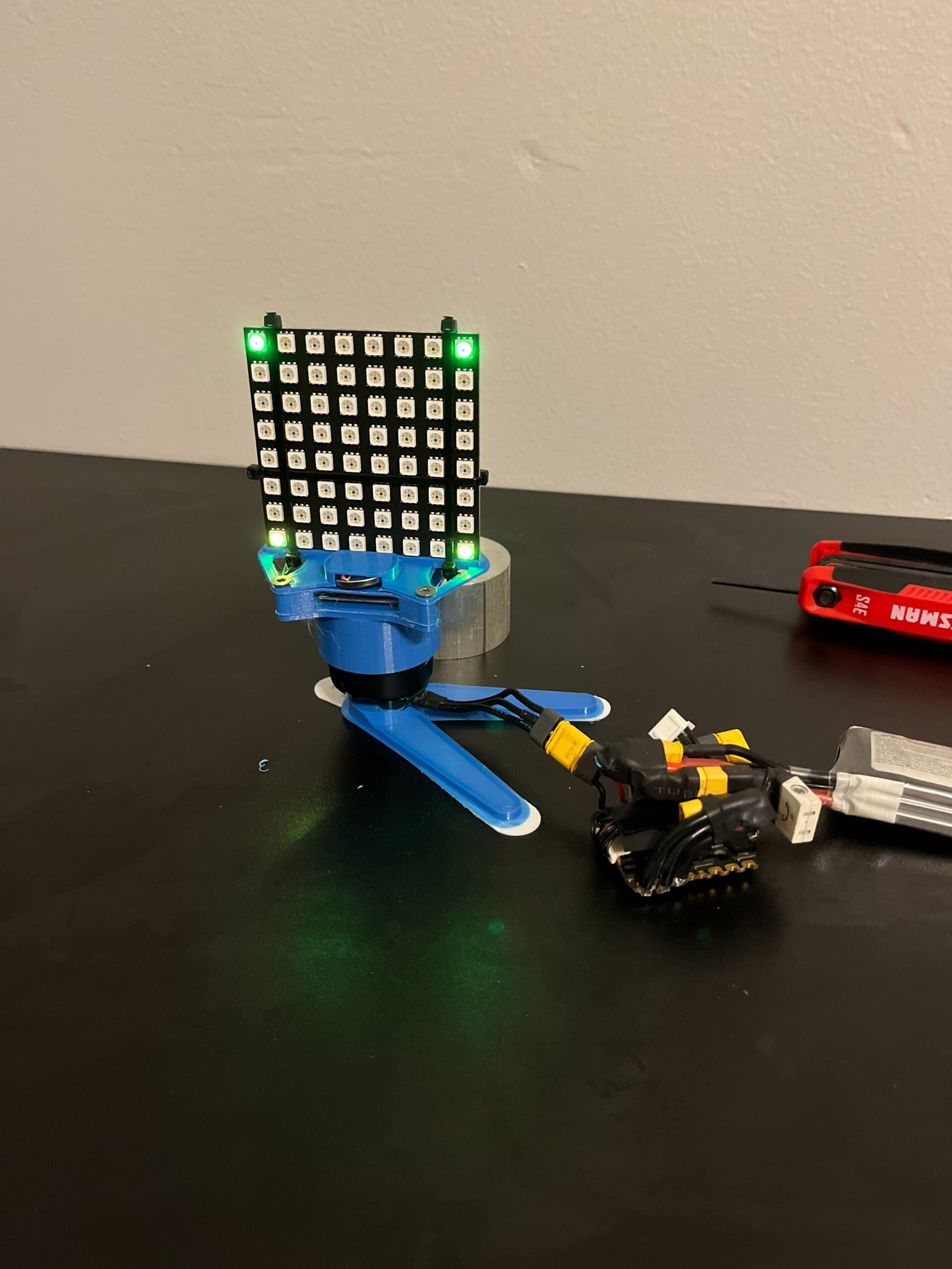
The spinning electronics are rather more complicated. The base of the system is a PixelBlaze controller with a 8×8 LED grid that is supports. Since these electronics are separate from the motor spinning the assembly it needed another way to know revolution speed. To get this information I used a cheap IR sensor that can detect an object as it passes each revolution. The power for the system needed to be cheap, small, and light since it was spinning fast. In my case I used a LIR2032 which I can recharge after each use.
Problems Overcome
This project came with many, many problems. To start, the Pixelblaze which had an option for a connector that integrated with the 8×8 grid had a 3 wire cable when the grid needed a 4 wire that’s soldered on. This was fixed by removing the port on the Pixelblaze and soldering 4 new wires between the LEDs and the controller.
The motors I chose also were way to small and since everything is mounted on the motor I didn’t trust its tiny bearings to keep everything upright. The solution to this was overkill, but it worked. I decided to swap to the spinner motor from my 3lb combat robot which is roughly 4x the size and I decided to use the control electrics from my robot as well since they are easily removed and already work. That also meant I now had control of the speed of the motor via a wireless controller.
The Pixelblaze has a learning curve to it since it runs on its one coding language. Fortunately the documentation was further down the page but it lacked some basic functions that I needed to i had to work around it. The most frustrating of which is a function analogous to millis() which in Arduino counts milliseconds since startup. The closest that was available is the time since last LED frame update which I summed each time it updated. This let me derive RPM based off the time between sensor readings and estimate the position in the rotation between sensor readings. Debugging this was rather difficult since the battery I had for the rotating part didn’t last very long so I was plugged in to the laptop directly. This meant I had to test spinning display without actually spinning it.
The final problem I encountered had to do with run time. The battery in my initial testing lasted less than 2 minutes, putting everything in power saving mode only got this up to 3-4 minutes. To get a longer run time I ended up disabling its onboard WiFi which was evidently drawing the vast majority of the power. The down side to this is that programming, or any settings change can only happen over WiFi. The final runtime is over 15 minutes with WiFi disabled.
Final Work
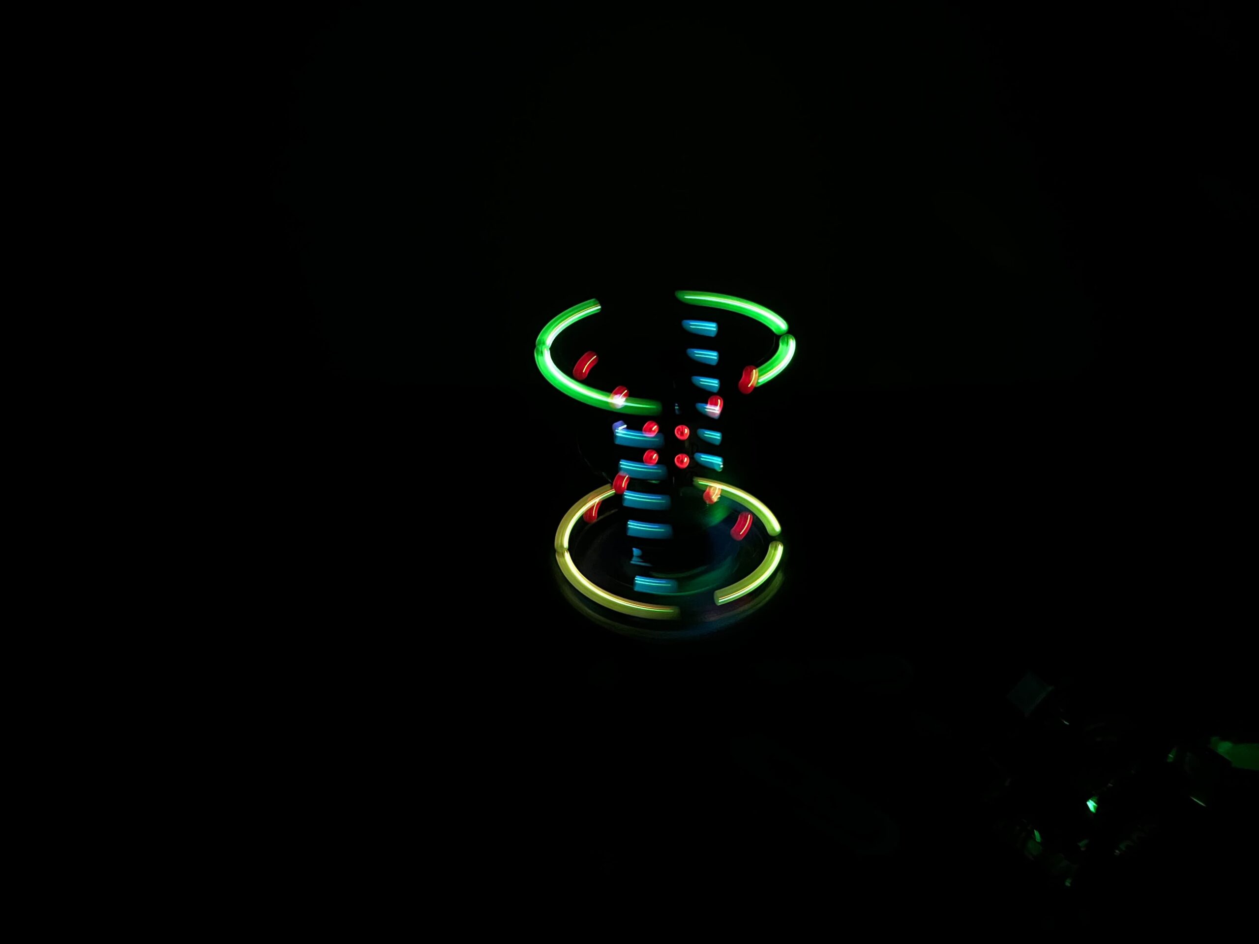
After lots of debugging and a couple iterations of 3d prints as well as zip ties to hold everything together it is done! A perk of the top spinning is you can’t see any of the mounting or wires, though they are still as neat as they can be.
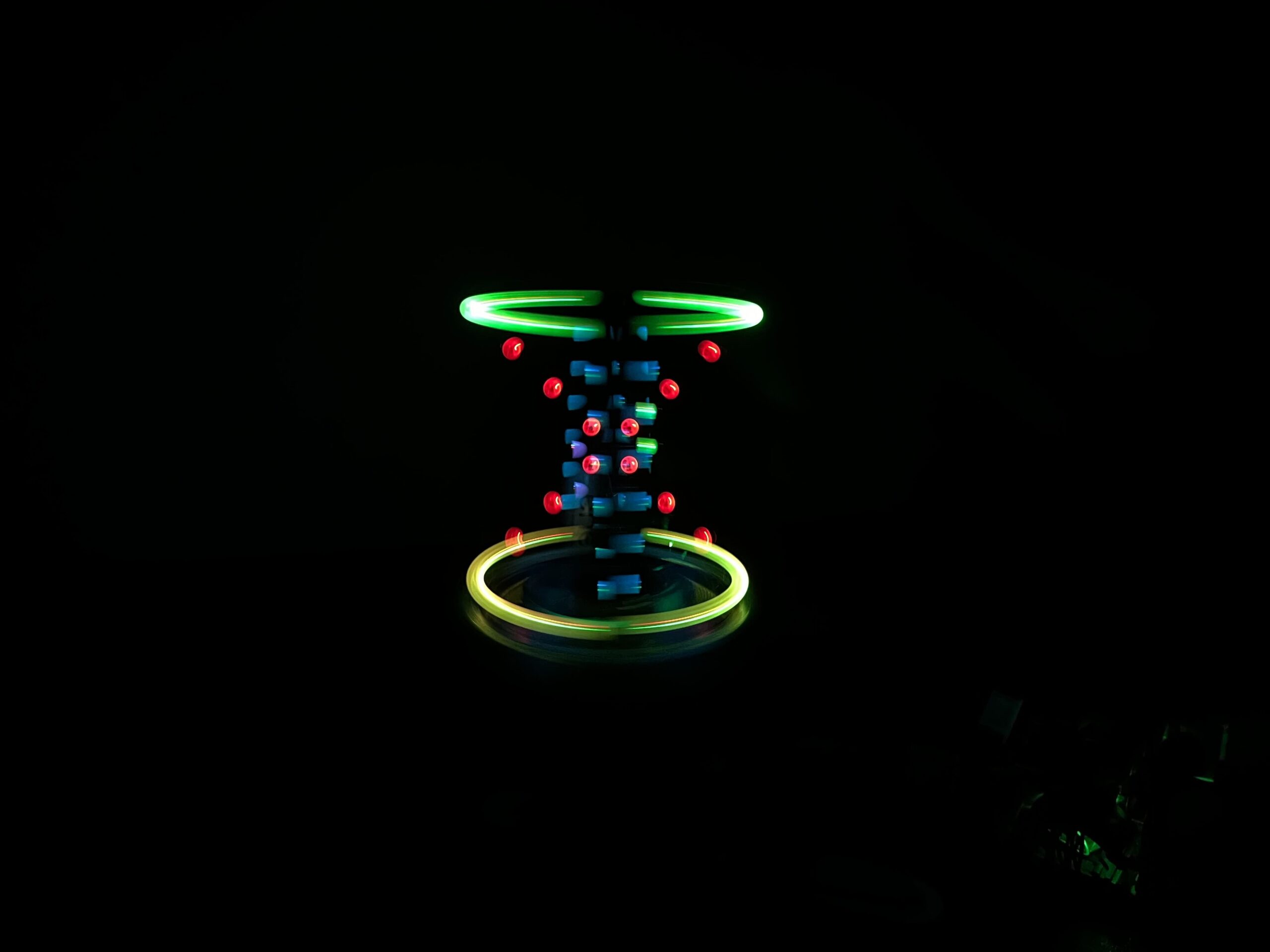
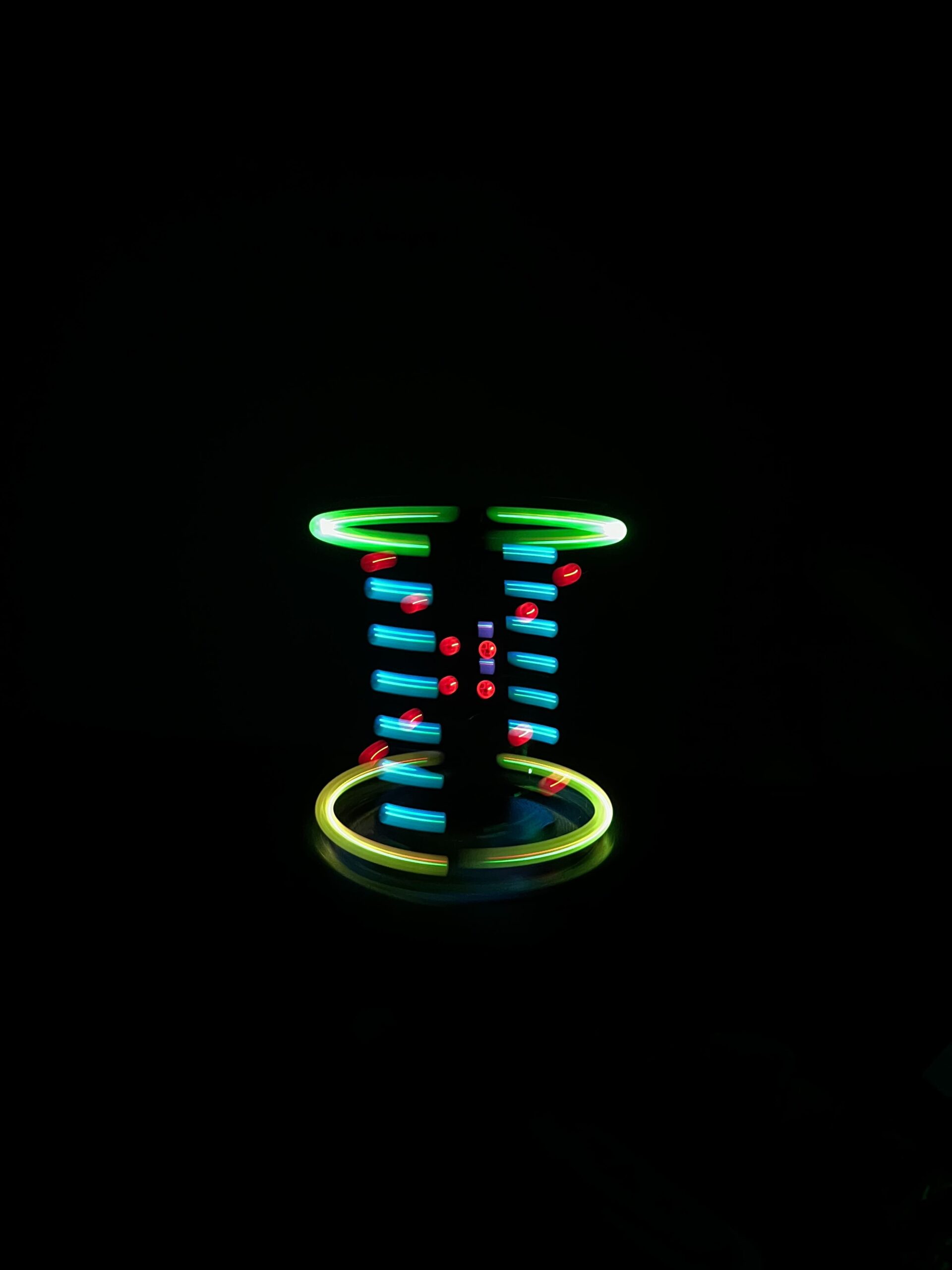
An feature of the final design is that the front of display tracks your finger or whatever object you put near the display allowing it to be interactive. For the final design to display I picked something fairly simple that would display well in 3D polar. On the plane as if it were a standard display I added a red X with a holding up a solid ring on the top and bottom planes. Since I thought of it as displaying a 3D model it needed to look structural so I added 2 Blue posts perpendicular to the X. Finally I added a moving component, 2 sets of dots that orbit the middle like an atom.
Overall I’m really happy with the final product, it works and looks very similar to what i had planned in my initial concept. Being able to display anything in 3D animated opens up so many possibilities for art. Unfortunately since POV relies on properties of how the eye perceives light, this will always be best experienced in person.