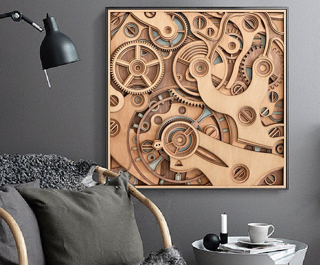
I wanted to include motion in this piece. I was inspired by laser cut gears that are layered in an intricate design. Even though it doesn’t look like this one spins it still served as motivation for my work.
I wanted to include motion in this piece. I was inspired by laser cut gears that are layered in an intricate design. Even though it doesn’t look like this one spins it still served as motivation for my work.
What is your plan for the location of the crank?
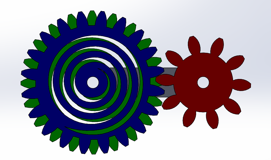
The crank will be attached to the red gear and when cranked, the other two gears will spin.
what are your thoughts on using that spiral as a built-in coil spring to add further movement?
I have considered that the design of my gears will have a coil spring built into it. I do not think that the coil spring will actually provide any play into this assembly. The blue gear will be make contact with the red gear at the teeth. The green gear will be belt driven from the center of the gear. There will be no extra resistance on the gears so it will act as a normal gear in theory.
this looks like it is going to take trial and error to get working properly. what are your plans for if it doesn’t spin? are you planning on using plywood, and if so, how do you expect that to effect the collision between gears since it is such a brittle material?
I am confident that this assembly should go together quite smoothly. I am modeling this entire assembly in SOLIDWORKS and am accounting for any additional clearances that I may need. I’m not too sure that I would classify plywood as brittle, but that is a good consideration.
What do you plan to use for pivots?
I will be 3D printing the pivots for the gears. I am also going to be experimenting with 3D printed bearings. I have had some luck with this in the past.
How did you do your design? It’s very cool.
Thank you! I had the idea in my head and made it come to life within a SOLIDWORKS assembly.
What materials are you planning on using?