Glowing Ferrofluid Patterns – Detailed Project Proposal

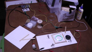
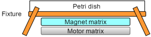
The block diagram of the chosen project, glowing ferrofluid patterns, is shown below. First of all, Processing will be used to extract the FFT data of a playing music track and transfer the FFT data to Arduino. On Arduino Uno, the FFT data will be quantized into six different frequency bins and the averaged amplitudes of the six frequency bins will drive the six vibration motors. The arrangement of the motors and magnets under the petri dish containing ferrofluid will be a pentagon-like shape since most petri dishes come in circular forms. After all that is done, the last task will be to 3D print a fixture to hold the petri dish so that the magnet and motor matrix can be inserted under the petri dish without touching it.

Untitled Diagram (5) Untitled Diagram (6)


Untitled Diagram (7)

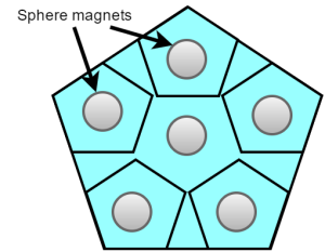
In the earlier version of the project proposal, it was proposed that nine motors will be used instead of six in order to add more freedom in the movement of the ferrofluid pattern; however, on second thought, the number of motors was reduced to six since an Arduino Uno that has six PWM output pins is already in possession. The physical shape of the magnets was chosen to be spherical so that the magnets can freely bounce and roll around within the confined pentagon shape when the motors underneath the magnets vibrate at different speed, resulting in more uniqueness in the change of magnetic field. Moreover, the vibration motors can draw up to 100mA at 5V full speed; therefore, it is required to have a separate power supply for the motors and this can be achieved by either using the power supplies in the ECE lab or purchasing a 5V battery for portability.

One challenge in the project is to design a medium between the magnet matrix and the motor matrix that will allow the sphere magnets to bounce around freely when the motors are vibrating. Since the motor discs are also made out of metallic element, the magnets will be sticking to the motors if a paper like medium is used. One way to resolve this challenge is to experiment the strength of the magnets as well as the attraction between the magnets and the motors and to even use a magnetic shield foil as the medium if necessary.

Picture1Picture2

Up to this point, all the necessary items in the following list have been purchased and I am working on extracting the real-time FFT data of a playing music track using Processing. The next step will be to get the communication between Processing and Arduino up and running with the FFT data.

Shopping List

  • Ferrofluid – 2oz
  • 6 Sphere magnets
  • 10 Glow sticks
  • 6 Mini vibration disc motors
  • Petri dishes


Project Progress (week 1)

In the past week, I bought the most important part that I will use in my project. This is the RGB LED light ring. I soldered wires to the ring and tested it. Below are two images of the setup. I connected the ring to a 5 volt power supply in the top right of the upper photograph. I also connected the ring to the Arduino in top left of the upper photograph.

LED_Ring_Test_1

LED_Ring_Test_2

For my project, I would like to have a rotating piece in the middle of the ring with parts on it that interact with the light. After thinking about many possibilities, I have decided to use 24 acrylic rods. Each rod will be mounted to a piece in the middle of the ring that will hold it directly above an LED on the ring. The 24 rods will be able to rotate around the ring.

These are the items that I need to buy before I can move forward with the project:

  • 24 3/16″ Acrylic Rods
  • 2 Gears: 1 large and 1 small (will connect a motor to the rotating center piece)
  • 1 Metal Rod (will hold the rotating center piece in position and allow it to rotate)
  • Wire in multiple colors


Dominic Cupo – Possible projects

Super late – My apologies


The first idea I have is for a TRON motorcycle. I like my motorcycle and would like to add EL tape and wire as well as LED’s to it. I could wire it up so that the lights would change depending on the RPM or MPH of the bike as well as other user inputs. To go along with that I would like to add EL tape and wire to my gear to complement the aesthetic. I could wire up lights on the jacket to flash with turn signals and brake lights for added safety as well as wow factor.

The next idea is a spinning LED ball. The idea is that there is a lattice of LEDs that spin along an axis. That entire armature then also spins around another axis perpendicular to the original axis. By varying the speed of the rotations and flashing the LEDs, you can create some very cool effects.

Finally I could do a silhouette shadow installation like Jim Campbell. It could see the people viewing it and replicate their shadows on the installation.

Construction_day1_12hrs

Construction Day 1

April 2, 2016

Cameron back

in order to acomidate my schedule with other classes, and to minimize appartment messes from the project, I have decided to take one day each weekend to work solely on the Flash EL suit project. the first day of work took place this past weekend, and took a total of 12 hours of work to complete.

I began on by first measuring myself to know my exact torso dimensions all the way around, then I turned the jacket inside out, and pinned the torso to fit these dimensions. I then sewed these gaps shut, and put it back to right side out, and was left with a jacket of the proper torso thickness. nice and tight, like the flash’s suit.

Figure 1.1  fitted jacket

I then moved on to the chest vinyl pieces. much like my previous work in the Green Arrow suit, I began taking pieces of vinyl fabric and cutting it into shapes for decoration of the suit. I went with the original design I revealed in my last post, and was left with an interesting design by the time I was done.

I would first start by measuring the chest of the suit, and determining the dimensions and shape of each piece, then would trace it out on the back of the fabric. I would then trace out tabs on the edges, and cut it out with the tabs sticking out. Then I just had to fold the tabs over, pin them to the back, and sew along the edges to “hem” the sides for a more professional look.


Figure 1.2  heming the sides           Figure 1.3   early padding

I started on the chest, then worked on some of the back padding from the initial sketches. I then covered the bottom of the suit, and left room for further improvements by NOT sewing the padding on yet. Instead I will continue pinning each piece on one at time, since this project requires very precise layering of the different padded pieces, and may need design changes mid way through, which will not be possible if they are each sewn on immediately.

Figure 1.4 Day 1 frontal          Figure 1.5 Day 2 back

Looking ahead, I would like for the suit to resemble more of the ‘Injustice: Gods Among us’ version of the flash than its original design had, since the design is starting to take physical shape more in that direction. I would also like to be able to cover up the zipper with a button-attachable chest piece, since I do not really like the way it looks with the large gap along the zipper. the following is my newest design plan, and will be the template I plan on using for this upcoming weekend’s work.

Picture11

Figure 1.6    Design plan 1

Figure 1.7    Design plan 2

injustice13-3wmuns

Figure 1.8    Injustice Flash


Artist Presentation

My artist presentation was done on Chul Hyun Ahn. He was born on January 15, 1971. He’s from Busan, South Korea and graduated from Maryland Institute College of Art. He’s known for installation art, sculpture, and light art. Ahn says he sits apart from other light artists because his objective primarily pertains to the creation of space, or rather illusion of space. Ahn’s main element of showing his art work is the one-way mirror. He calls the mirrors, “the barbershop-mirror effect.” He only uses fluorescent lights. He has a few different art series like the forked, vertical, mirror, and etc. Some of his art work is shown below.

1

2

3

4

5

Project Ideas

My first project idea is to create a Tin Can Lantern. I would take an old recycled tin can and spray paint the can and use a drill/nail to cut out different shapes and patterns. I plan to use some type of lighting system that would make the wholes reflect a shade/shadow, but I am not sure with I am going to use for lighting right now. But the project would come out looking like something, shown in the picture below.

Can lighting

My second project idea is to create a Mason Jar Solar Lantern. I would buy a glass jar and super glue marbles to the outside of the jar. The marbles would light once the solar cap gets enough sunlight. If I can not do the solar cap I will find another way to light the marbles. When the marbles light up it will make a light reflection, shown in the picture below.

Mason Jar Light

My third project idea is shown below. I don’t really know what it is, but I found it online and it looked really cool. Looks like its made with string and has some type of light shining on it. But if I were to do this project I can either make it with string or I can use LED lights to make different patterns.

Line Lighting

Project Idea

For my project I would like to make a three dimensional EL wire sculpture of a dinosaur. I will achieve the volumetric shape by using rings of light. I want combine different colors of El wire to give detail to the dino. The structure would be make out of steel wire which means that the piece should be poseable and I may be able to put a motor in the head so that it can move. The sculpture will be hooked up to a sound based inverter so that the brightness will vary with music and noise. I can also do a bunch of different variations such as using a sequencer to cycle through different parts. Alternatively I could use two different sound inverters with different thresholds so that different parts react differently. I know I want to do the sculpture but I’m still not sure about what effects I want to go for and what size it should be.20160401_152712

Cameron Back – Flash concept

For my project, I would like to create a character costume which applies EL wire and related electronics to enhance its design.

for this project to be as cost effective as possible, I preemptively purchased several different vinyl (leather-like) fabrics and materials. All were purchased based on their cost and availability before arriving back on campus for this term. These include:

  • 1 yard Dark red vinyl
  • 1 yard Deep red vinyl
  • 1.5 feet Goldenrod vinyl
  • .5 yard Thin yellow lining
  • Sound sensitive EL wire pack
  • Red base jacket and pants

The total cost is estimated to be: ~= 28 $ fabric + 30$ suit = 58$

Picture1

So when choosing characters for the costume, I had to make sure the choices would be close enough to the chosen color scheme first. This narrowed down the search significantly. Then, after searching through tons of artwork, and comic book material, I chose to make my costume after the Flash.

Picture2

Specifically, my plan is to use the EL wire and related sensors, to make the lightning designs around the suit illuminate in reaction to sound and/or speed (as shown above).

Choosing this particular character is a good choice, since in the past, there have been no recorded costumes at comic conventions at this level, other than the flash tv show replicas sold online.

Picture3 Picture4

my suit will be of much higher quality than anything seen before, and will be 100% unique in its design. It will also showcase elements from several of the character’s previous designs. having been around since 1940, the flash has seen tons of faces, designs, and incarnations over the past 75 years.

Picture8Picture7Picture5

Picture6

My current design is shown bellow, and pays tribute to several of these designs, while keeping in mind the limits of the EL wire and other hardware needed.

Picture11

These designs are not final, but I hope to begin work on the suit very soon, and can not wait to show you all more!