After buying all the items I need for the project, I started working on getting the software part of the project working. As outlined in the Project Proposal, the first step was getting Processing to output the FFT spectrum of a playing music track on my laptop. There were a lot of helpful tutorials online and they helped me get the real-time FFT data of the song/microphone input. After, looking around what others have done for Arduino-Processing Spectrum Analyzer projects, I realized that the highest frequency content of the spectrum is about 5kHz for most songs instead of the full human hearing range of up to 20kHz. Therefore, I divided the frequencies from 0 to 5.6kHz into six frequency bins in Processing as shown below.

The frequency bin heights were limited from 0 – 255 to be compatible with the Arduino PWM write function. Different scale factors were used for the human voice bin and the low frequency treble bin since they were pretty small compared to the bass height. A real-time visualization of the FFT spectrum can also be plotted on Processing. 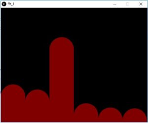
Now that these frequency array values are ranging from 0 to 255, I sent them to Arduino using a for loop. Before each iteration of sending data, 0xFF was sent first for synchronization purposes. In Arduino, the code was written so that Arduino starts reading data by byte once 0xFF was recieved through the serial port. Equal for loop delay of 5ms and main loop delay of 10ms were added in both Processing and Arduino scripts to further ensure the data transfer synchronization. It was confirmed that the data transfer between Arduino and Processing was synchronized by sending constant input from Processing and observing the same output at Arduino.
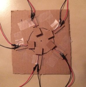
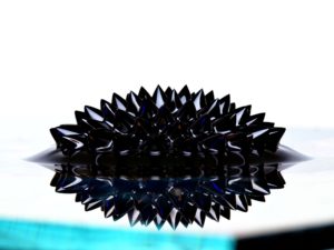
Now that the software part of the project is mostly done, I started working on the hardware part, which is the vibration motor matrix and how the motors come together with the sphere magnets and the petri-dish containing ferrofluid. Using cardboard boxes, I tried to make a fixture for the motor matrix. Little did I know was that there is a considerable attraction between the ferrofluid and the magnets as well as the motors, which means that the plan to vibrate the sphere magnets to change the magnetic field is not gonna work since everything is sticking to one another…
So I thought about changing the magnetic field without having any moving parts, which leads me to the idea of using electromagnets instead of permanent magnets. Having spent about 35 dollars on the sphere magnets and vibration motors, all of which have become useless now, I was actually hesitant on buying new materials, so I went ahead and bought six of these small and cheap electromagnet brakes from Amazon shown below with two day shipping.
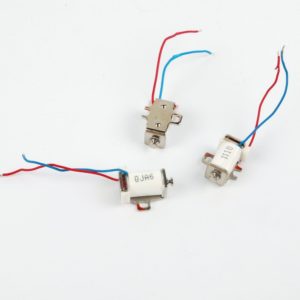
It turns out that the magnetic field they produce is too small and nothing but a small bump appears on the ferrofluid when they are powered. Another 27 dollars was wasted…
At this point, I was pretty disappointed because I have spent so much money and nothing really seemed to be working as I expected. I knew I needed a strong electromagnet but I have no idea how strong and how much money I should be spending. I saw some Youtube videos testing some lift electromagnets and thought I should give it a try. So I purchased three of the 12V 5.6lbs lift electromagnets from Amazon with two-day shipping.
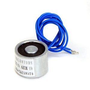
By using a transistor and a 12V power supply from AK227 lab, I was able to control the strength of the electromagnet with Arduino. With only ferrofluid in the petri-dish, the movement of the ferrofluid due to the changing magnetic field strength from the electromagnet looks like this following video (It’s not my experiment, I forgot to document this phase). Instead of the spikes as in the case with a strong rare earth metal, a rather large bump was witnessed even when the electromagnet is at full power (12V, 0.25A).
At this point, I was quite happy with the results since I can see the change in the magnetic field with the incoming music FFT data. But I was not quite satisfied because I thought I was gonna see the spikes with this electromagnet since it is relatively strong. Also, I know that without the spikes, I would not see the cool patterns even when I put the glow material into the ferrofluid.
I did more research online looking for an explanation of why I am getting just a bump and not spikes with the electromagnet but to no avail. Then, somewhere on the Amazon website, I also saw this ferrofluid suspension in a bottle filled with water-like liquid. At this point, my plan has changed from hunting for the ferrofluid spikes to just creating a cool visual by turning on one electromagnet of the three I have at a time and make the ferrofluid chase the electromagnet that is turned on. The light art aspect of this idea would be to just use a RGB led to light up the water-like fluid part with incoming music data.
So I did more research about what that water-like fluid is, and it turned out to be 70% isopropyl alcohol. I have a bottle of 91% isopropyl alcohol sitting in the bathroom closet so I tried with that but it does not seem to work as the ferrofluid just sinks to the bottom and smears all over the container as I drag the magnet around it. So, I took a quick trip to the local CVS and bought one of the 70% isopropyl rubbing alcohol and it worked. Then, I tested it with the electromagnets that I bought and little did I know that it would also form spikes when the electromagnets are powered on. I hooked the experiment up with my laptop and Arduino and start playing songs with really nice beats. The results are below…
This first one is with all three electromagnets being driven with the bass FFT data.
The following ones are made with bass, voice, and low frequency treble data. Can you tell which one is which?
I know it is hard to see because it is clear, but the 70% sopropyl rubbing alcohol is in the cup. Also, I used a plastic cup because I did not have a glass petri dish.
So once again, and I hope this is the last time, I went onto Amazon and bought three more of the same electromagnets that I already have and 5 glass petri-dishes and a jar of glow paint since getting the glow material out of the glow sticks is extremely messy and difficult.
At this point, I think the majority, or at least the hard part, of this project has been accomplished and I have spent $193 with about $60 spent on items that are not gonna be used at all. Looking forward, I will include the Light Art aspect into it by first using the glow paint with the 70% isopropyl rubbing alcohol. I am not sure if that is even gonna work since it’s not really mixing the paint with water but if it did not, I will use an RGB led and light the glass petri-dish from the bottom and have the RGB led change color with the music.
Here is also a picture of the setup in AK227 lab. For the project demonstration, I will have to borrow a 12V power supply in order to power up the six power-hungry electromagnets.

